
Linear buckling typically occurs when there is a sudden loss in stiffness due to compressive loading. It’s a problem that you swiftly want to avoid within your designs – so let’s take a look at its root causes and how to mitigate the problem.
As an engineer, designing around failure modes will likely involve some form of finite element analysis (FEA). In order to analyze the factor of safety properly on an element, however, you need to identify the failure mode. While yielding is certainly the most common, it’s not the only mode of failure. Yielding tends to be somewhat predictable in a material, but other modes of failure like linear buckling can occur suddenly without any warning.
Linear buckling has the possibility of occurring on any thin member of a design. Its root cause lies in the thickness of the member in relation to the stress elements. As a small displacement occurs internal to a member due to an applied load, there appears a stiffening within any given element. This loading produces a stress dependent stiffening effect which compounds onto the linear static stiffness of the member. When the stress-dependent stiffness internal to a member overcomes the linear static stiffness, buckling occurs. To explain it more simply, when a component is placed under a load that causes large internal stresses relative to the material stiffness, it buckles.
Now that we understand how and why a component linearly buckles, let’s look at the analysis techniques you can use to determine if a member in your design is at risk.
When determining how or if a component will fail through linear buckling, one needs to find the first positive buckling mode. There may be many buckling modes for a component, but due to the catastrophic nature of buckling failures, a component will likely never undergo more than one buckling event. As a program undergoes FEA, it calculates the buckling load factors to produce the ultimate load magnitude. This load is almost always overestimated in analysis and the results output are normally nonconservative. Most FEA programs analyze a component as a smooth solid member without imperfections. In actuality, manufactured parts have imperfections – whether that be a chip or an uneven face. As a result of the combined imperfections in the analysis from minor mathematical flaws and more major modeling issues, the results of Linear FEA tend to be more cautionary than absolute.
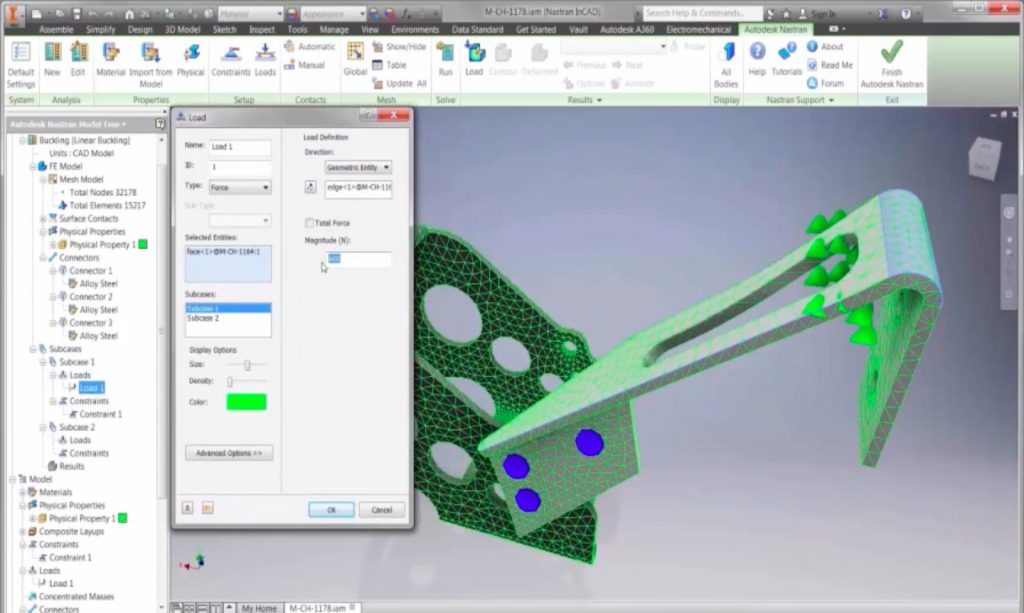
With the implementation of Nastran In-CAD inside of Inventor or SolidWorks, problems of linear buckling can be solved as part of your normal workflow. After completing your yield analysis on a member, you can simply change your stress analysis to a linear buckling type. This allows you to keep your previous loading conditions and determine the maximum loading before a part buckles. You can see more in the video below.


Add comment
Connect with: Log in
There are no comments