Did you create a sweep with Autodesk Inventor today?
It’s a trick question (I know you did) but you may not have used the sweep command to do it… I’ll explain later.
In this blog post series ‘Get Smart with Inventor Part Modelling’ we will find out how Inventor generates shapes for us, to gain a better understanding of how we can achieve the geometry we want.
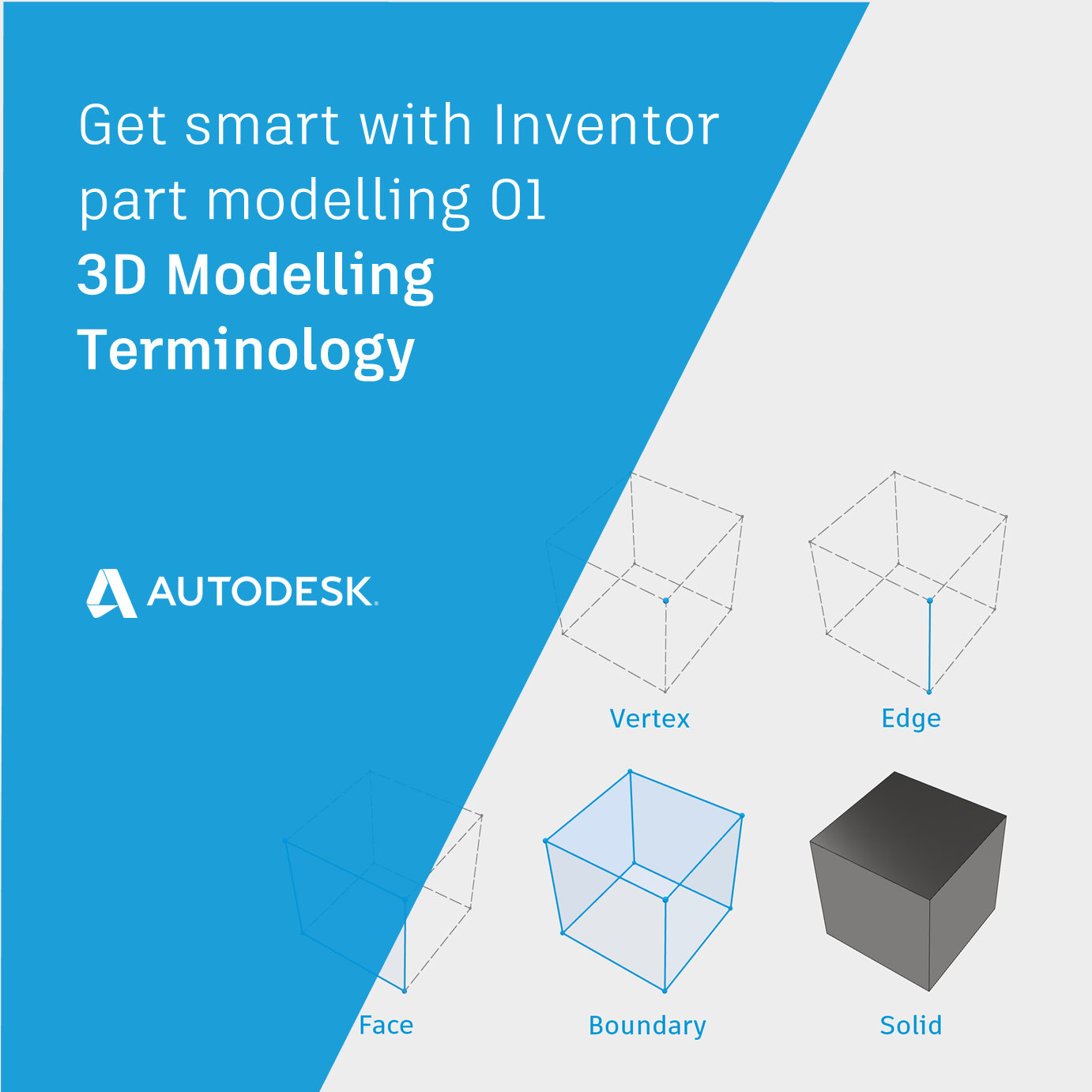
In this post ‘3D Modelling Terminology’ we will make sure that we are all using the same language when discussing the shapes that we build with Autodesk Inventor.
If you have learned the basic Inventor 3D modeling commands and you are ready to create more complex part models, this article will help!
Introducing the Autodesk Shape Manager (ASM)
To generate 3D shapes, Autodesk Inventor calls on the Autodesk Shape Manager (A.S.M).
ASM is a modeling ‘Kernel’ – a component that calculated 3D shapes.
Fun Fact! ASM is also used by AutoCAD and Fusion 360 (among others).
ASM uses the ‘Boundary Representation’ (Brep) method of calculating shapes. Breps are shapes based on Vertices. Two vertices can define an edge. A loop of edges can define a face. A collection of faces defines a volume (a 3D shape).
When we create 3D forms In Inventor using commands such as Extrude, Sweep or Loft – we are using the Inventor user interface to pass coordinates to ASM, which generates a Brep and passes it back to Inventor to be shown on screen.
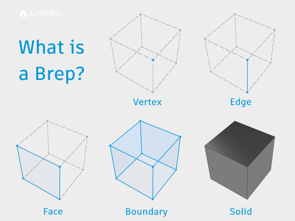
What is a BREP?
3D Modelling Terminology
Let’s make sure that we are all using the same 3D Modelling Terminology when we talk about shapes inside Inventor.
Geometry & Topology
Geometry can be thought of as the shape we want to create. Topology is how we get there.
The same geometry can be created using different topology. The same topology can be used to create very different geometry.
- Geometry – the mathematics that describes the shape.
- Topology – The vertices, edges, and faces that form the shape.
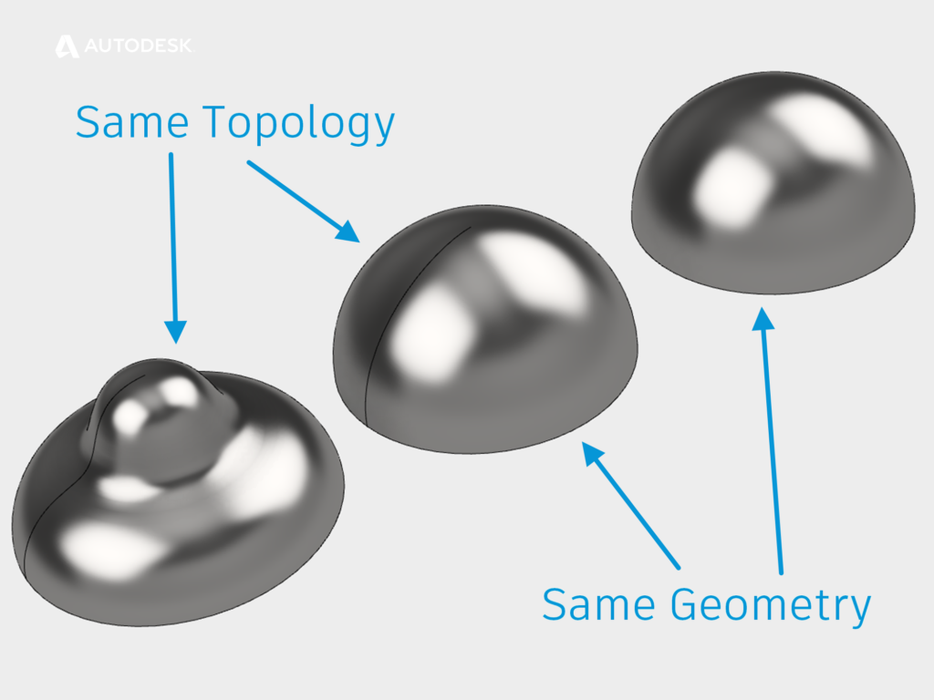
Topology Vs Geometry
Surface Normal
The normal direction of a surface is perpendicular to an edge or face.
For a solid model, the normal must always point ‘outwards’ from the solid volume.
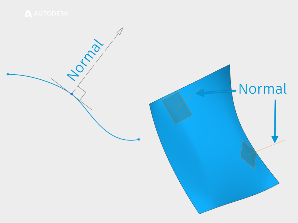
Surface Normals
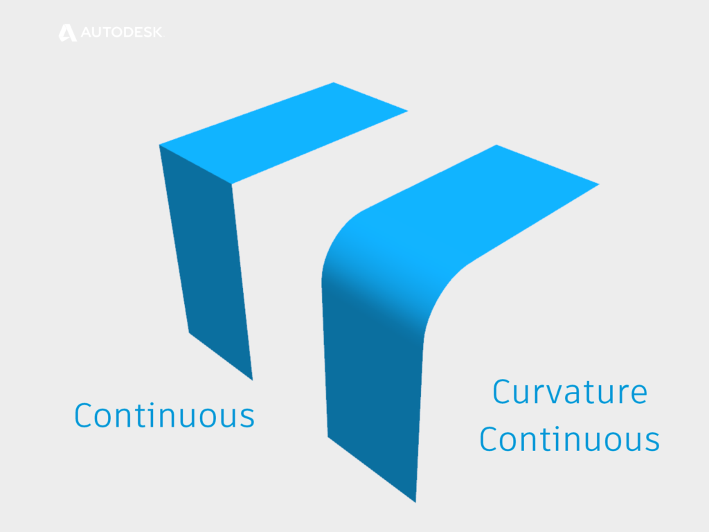
Curvature Continuity
When we would like to create a smooth transition between to surfaces, we can describe the condition as ‘Curvature Continuous.’
Curvature continuity is the process of matching properties across two surfaces. We describe these properties using the letter ‘G.’
The properties are accumulative – G3 continuity includes G2, G1 & G0.
- G0 Continuous – The edges meet (also known as Touching or Position).
- G1 Tangent– The surface normal match along the meeting edges (A fillet).
- G2 Curvature– The amount of curvature matches along the meeting Edges.
- G3 Acceleration – The rate that the curvature changes are equal leading into the meeting edges.
Note: G+ Mathematically you could describe additional levels of ‘G,’ but they won’t help us create awesome models.
Curvature Continuity
Why (almost) every shape is a sweep | Get Smart with Inventor Part Modelling 02
Click this link for part two of ‘Get Smart with Inventor Part Modelling,’ in which we will take a closer look at how Autodesk Inventor’s 3D modeling tools work under the hood (and I’ll explain my cryptic comment about sweeps…)
This blog post is based on an Autodesk University class, originally by Jake Fowler and later updated by Inderjeet Wilkhu and Paul Munford. You can watch a recording of the class, and download a handout that goes with this presentation from the Autodesk University website here:
Autodesk University Online: The Inventor 7 Deadly Sins of 3D Part Modeling


Congratulations, Paul, on your first published post on the official Autodesk Inventor Blog. Well done!
Thanks Jerry :)