
What you don’t know about High Efficiency Roughing vs High Speed Roughing is costing you money
It is often joked that you can tell a good machinist from an average machinist by their Kennedy toolbox. However, what is not a joke is that a good machinist can hear the difference between a high quality and poor quality cut from across the shop. This is especially true when performing traditional roughing operations. These cutterpaths often contain variable chip loads, varying step overs, and -too often -full diameter width cuts.
Traditional roughing passes are characterized by using a series of offset radial passes. These passes are calculated by offsetting a planar cross section of the CAD geometry and stock model when necessary, then merging and trimming the two together. With this approach, regardless of the offset step over value used, the tool will see increased cutter engagement at every internal corner or when driving into slots. These internal corners and slots are where cutter forces spike, and when the tool is most prone to breakage. In order to operate at a high feed rate while using traditional roughing strategies, the programmer needs to take a shallow axial depthof cut. This can create other tool issues, as you are now overusing the bottom of the cutter, rather than the whole flute length. This causes the tool to store more heat in the bottom, versus spreading it out along the whole flute, causing premature wear.
In contrast, constant cutter forces maintain a constant radial tool engagement throughout the entire cut. Constant radial tool engagement eliminates spikes in the cutting forces. This allows the programmer to take a larger axial depth of cut, while simultaneously maintaining a high feed rate, and extend tool life overall.
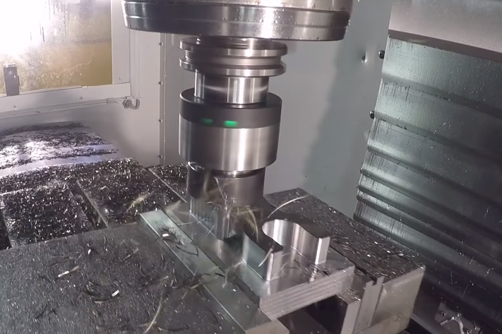
To get some real world data, we used the Autodesk shop facility at Pier 9 and logged data from a SPIKE sensory tool holder while cutting 1018 steel. Inside the tool holder is a SwiftCarb solid carbide end mill, with everything running on a Haas VF2SS vertical machining center.
First, we ran the part using a traditional roughing approach. Not only can you hear the 4variation in the cuts, but you can clearly see it in the logged data. Here the tool holder sensors show a tale of cutter loads with considerable variation, and very sharp spikes, especially in torsion (green) and bending moment (red) in the displayed graphs (Graph is blue –axial force, red –torsion, green –bending moment)
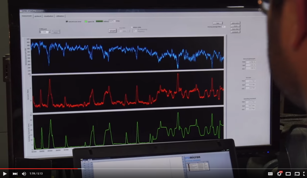
Machine operators need to adjust their feed rates down for the worst case scenario, which can be visualized by the spikes. However, this means for the rest of the operations, the program is not running at optimum material removal rates, as the manylow areas show. If we use our high school pre-calculus, we know that the area under the graph is what is actually important to us. The more area under the graph, the more material that is being removed, and the more efficiently you are running. Looking at the graph, there are a lot of areas that are low and flat, indicating inefficient areas, with the occasional spike of higher material removal.
Constant cutter forces quickly reach the maximum efficient machining rate, and maintains that rate throughoutits cut. Then repositions for the next cut. This allows milling at an efficient rate during all cuts, with constant cutter forces throughout the cut. Constant forces mean less vibrations within the tooling, and less shock to the cutting edges caused by those vibrations. This extends the tool life, and reduces tooling costs.
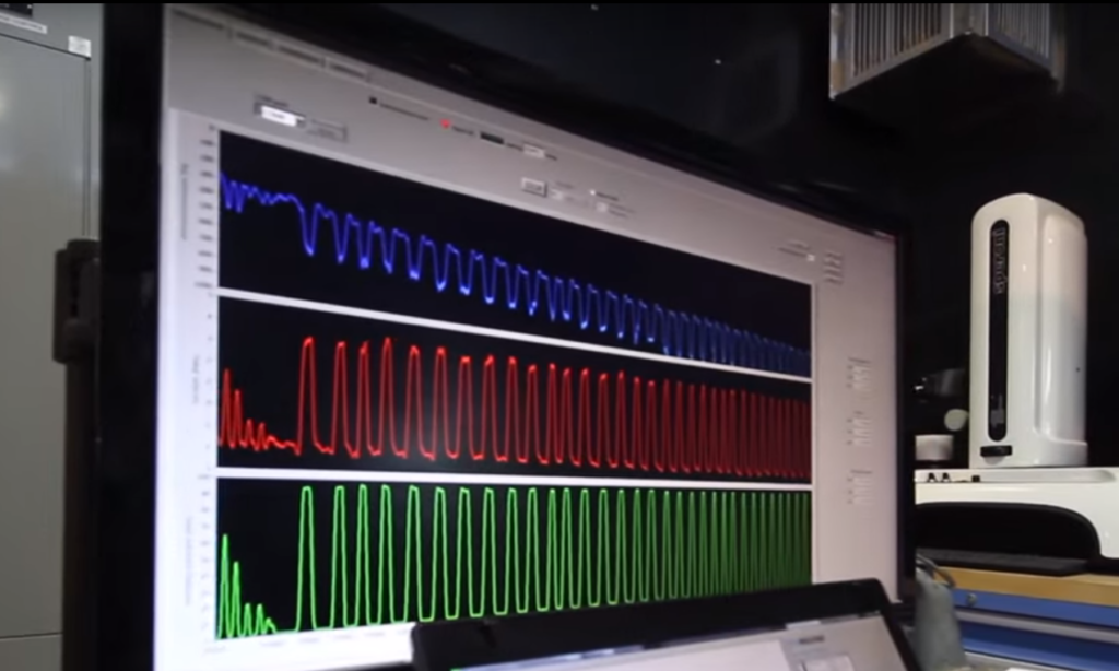
The graph shows consistency between when the tool is cutting, in all cuts, and when the tool is not cutting. Comparing the area under the graph, one can readily see that the tool spends more time at a maximum efficiency cut, creating more area under the graph.
In real numbers, what this means is that the traditional roughing pass took 8:09 minutes to complete the roughing operations, while the adaptive clearing technique took only2:01 minutes.
While saving time is huge, the benefits go deeper than that, including reducing tool wear and breakage, while also having more predictable cutting conditions. Because we are able to use a larger axial depth of cut, we are able to utilize more of the cutter flute length, without overusing the bottom or corner of the cutter. Additionally, the generated heat is spread out along the whole cutter flute length, rather than being concentrated at the bottom of the tool.
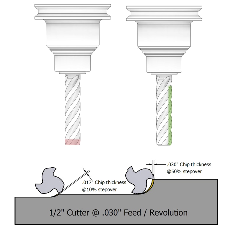
Achieving a high metal removal rate (MRR) is the goal and is how we reduce cycle time. Higher axial cut depths require lower radial cut values to allow for reliable chip evacuation. By reducing the radial depth of cut you are able to increase the tool flute count and increase the metal removal rate. By reducing the radial depth of cut you are also able to use chip thinning calculations to increase the cutter feed rate to maintain the chip thickness. A thicker chip will also pull more heat away from the tool.
Without spikes in material removal rates, setting feed rates for maximum material removal becomes much easier. You can use the data from your tool supplier, or simply start milling, and increase the feed rates slowly to a level you are comfortable with. We like to dothis after making the first pass around your block, in case your stock size was a little different than what you programmed for.
When dealing with molds with complex 3D shapes, using the large depth of cut will leave larger “stair steps” in your roughedmodel. In situations like this, make sure to take advantage of Step-Up functionality so that your roughed stock has a consistent stock allowance.
Adaptive Clearing utilizes a strategy of constant cuts with a repositioning move. The inherent benefit is that you always maintain a climb cutting direction, where in traditional roughing operations there may be periods of conventional milling cuts. Because of this, there may be a more retracts than some people are accustomed to when the reposition is over a greater distance. Generally rapid retracts are fastest, however, you can also modify stay down parameters. With these parameters, the tool will not retract to the top of the stock, but rather stay down as it repositions. In many cases you want the tool to lift slightly to avoid dragging the floor during repositioning moves which could generate undesired heat and premature tool wear.
Increasing metal removal rates, decreasing cycle times and improving cutting consistency is easier than ever before with Adaptive clearing strategies. Adaptive clearing strategies are easy to implement and test because; first, they do not require special tooling. Second, they don’t require a special mill; they work well on entry level mills as well as the fastest high performance mills. Lastly, they are available for a wide range of CAD systems including SOLIDWORKS, Inventor and Fusion 360.
View the original article on MoldMakingTechnology here.

Add comment
Connect with: Log in
There are no comments