
Introduction
Previous Blog Posts have shown the usefulness of Mesh Adaptivity and the effect of Mesh Settings on simulation within the context of Mesh Convergence. Here we will extend that discussion to show the Simulation times that should be expected for a range of additive geometries using Netfabb Simulation. These parts include a simple bracket, a large impeller, and a generatively designed automotive bracket, each shown below:

Figure 1 Simple Bracket
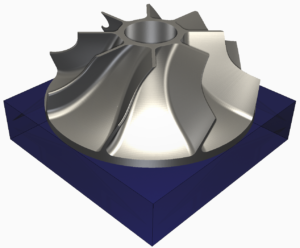
Figure 2 Impeller
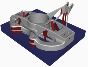
Figure 3 Automotive Bracket
The STL files for these geometries are available to download here in the Bench Mark Model Files.zip so that this study can be replicated by our users.
Simulation Settings
All 3 geometries are simulated using the following simulation settings:
- PRM File:Generic Inconel 625 settings: 250 W 800 mm/s 40 micron layer thickness
- Build Plate: Inconel 625, 25 mm thick
- Boundary Conditions:
- No build plate heating
- Estimated Heat Loss Thermal Boundary conditions, Mechanically fixed build plate
- Plasticity: Off
- Heat Treatment: None
- Automotive Upright Support Structure Volume Fraction: 0.01
Two sets of mesh settings will be shown for each model, one coarse, one fine. The coarse setting is the coarsest mesh which shows convergence while the fine settings are set to better capture the curvature of the test parts.
Mesh settings
The mesh settings and resulting mesh size for the 3 example geometries at both mesh settings are given below:
| Model | Mesh Detail | Layers Per Element | Coarsening Generations | Final Node Count | Final Element Count |
| Simple Bracket | Coarse | 25 | 1 | 44165 | 23134 |
| Impeller | Coarse | 16 | 1 | 179141 | 90208 |
| Automotive Bracket | Coarse | 13 | 2 | 698385 | 380187 |
| Simple Bracket | Fine | 18 | 1 | 75861 | 41422 |
| Impeller | Fine | 8 | 1 | 681877 | 329974 |
| Automotive Bracket | Fine | 9 | 2 | 1637118 | 951987 |
The Resulting meshes can be seen below:
 Figure 4 Simple Bracket Coarse Mesh Figure 4 Simple Bracket Coarse Mesh | 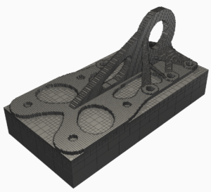 Figure 5 Simple Bracket Fine Mesh Figure 5 Simple Bracket Fine Mesh |
 Figure 6 Impeller Coarse Mesh Figure 6 Impeller Coarse Mesh |  Figure 7 Impeller Fine Mesh Figure 7 Impeller Fine Mesh |
 Figure 8 Automotive Bracket Coarse Mesh Figure 8 Automotive Bracket Coarse Mesh |  Figure 9 Automotive Fine Mesh Figure 9 Automotive Fine Mesh |
Simulation Results
The magnitude of displacement results for the 3 examples are given in the following figures. The result increment is after manufacture and the part has cooled down to room temperature. The mesh edges are turned off for the Automotive upright so as not to cover the simulation results.

Figure 10 Simple Bracket Coarse Displacement Results

Figure 11 Simple Bracket Fine Displacement Results
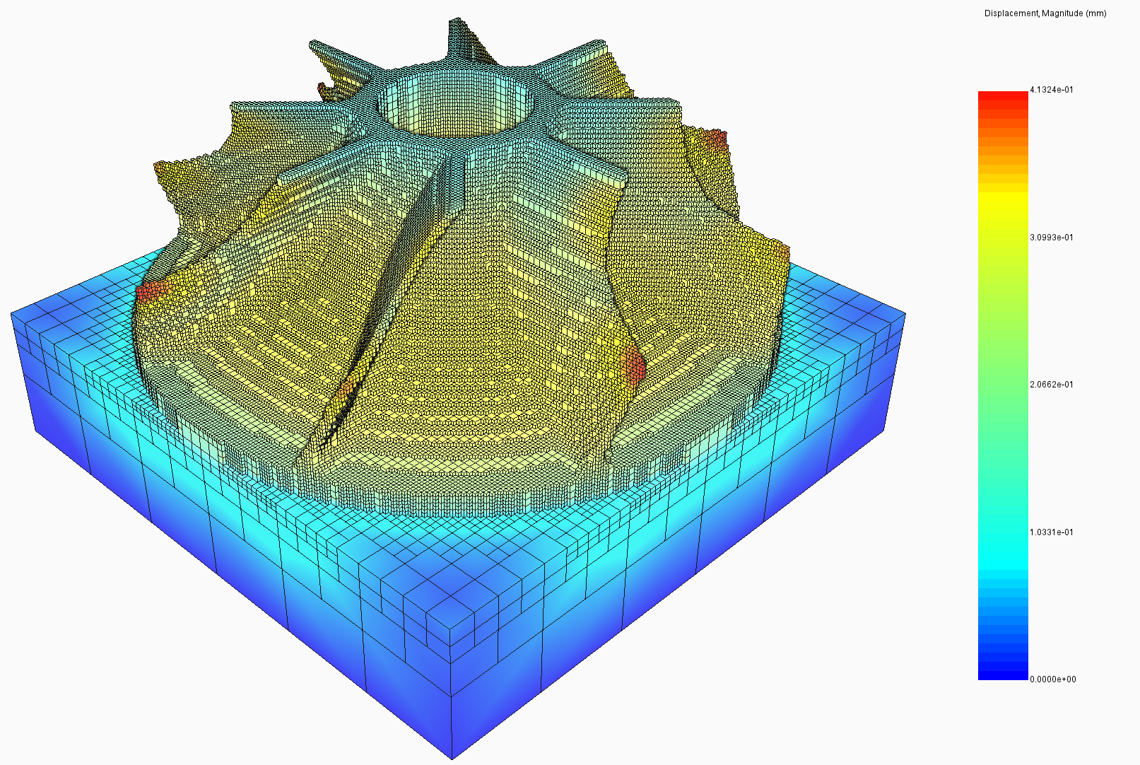
Figure 12 Impeller Coarse Displacement Results

Figure 13 Impeller Fine Displacement Results

Figure 14 Automotive Bracket Coarse Displacement Results
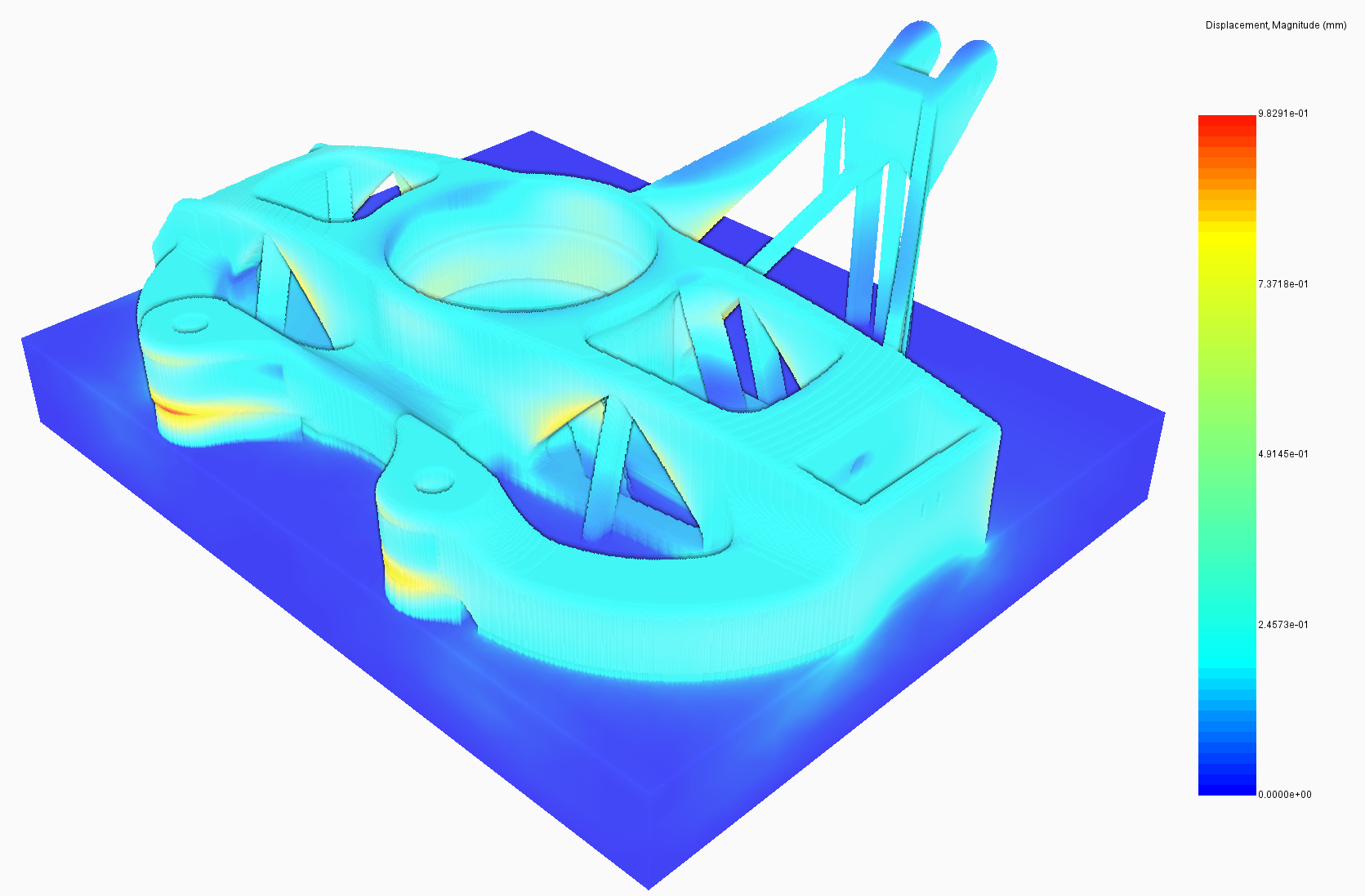
Figure 15 Automotive Bracket Fine Displacement Results
In the table below simulation times are given, along with an estimate of the time it would take to additively manufacture each geometry, and a ratio of time to simulate vs the estimated time to build each part. Build time estimates are calculated by the solver from the volume of the part and the processing conditions. These estimates do not include any lead in time prior to the start of manufacturing or post processing cooldown time. All simulations were completed on a 14 core Intel Xeon 2.2GhZ processor.
Computational Times
| Model | Mesh Detail | Peak RAM Usage | Simulation Time | Estimated Build Time | Percentage of Simulation to Build Time |
| Simple Bracket | Coarse | 0.98 GB | 2 min 13 s | 9 hours 43 min | <1% |
| Impeller | Coarse | 3.76 GB | 8 min | 15 hours 12 min | <1% |
| Automotive Bracket | Coarse | 10.7 GB | 38 min 34 s | 1 day 5 hours | 2% |
| Simple Bracket | Fine | 1.86 GB | 5 min 13 s | 9 hours 43 min | <1% |
| Impeller | Fine | 16.2 GB | 47 min 50 s | 15 hours 12 min | 5% |
| Automotive Bracket | Fine | 42.7 GB | 3 hours 1 min | 1 day 5 hours | 10% |
Conclusions
This exercise has shown Netfabb Simulation users the expected run times for 3 benchmark geometries using 2 mesh settings each. This should assist current and potential users in creating an expectation of simulation speeds on their machines. It has been shown that even for a large complex geometry using very fine mesh settings 10 different simulations can be completed in the same time as it would take to print the actual part. This computational speed allows users to attempt various orientation, support, and even geometrical choices before committing to printing finalized parts.


Add comment
Connect with: Log in
There are no comments