Back in April of last year, I wrote a post on this blog showing how you can modify the DefaultConnectorsConfig.xml file to allow different flange pressure classes and facings to connect together with AutoCAD Plant 3D 2015. Some of the modifications were through Project Setup, while others required editing the XML file directly. When AutoCAD Plant 3D 2016 came out, some improvements to the XML file were implemented by our developers. These improvements mean that there are some additional things you will need to manually edit in the XML file to allow your connections to function as expected.
In the previous post, I used a flanged connection as my example. Using that same example where we have set matching values for the pressure class and facing in Project Setup:
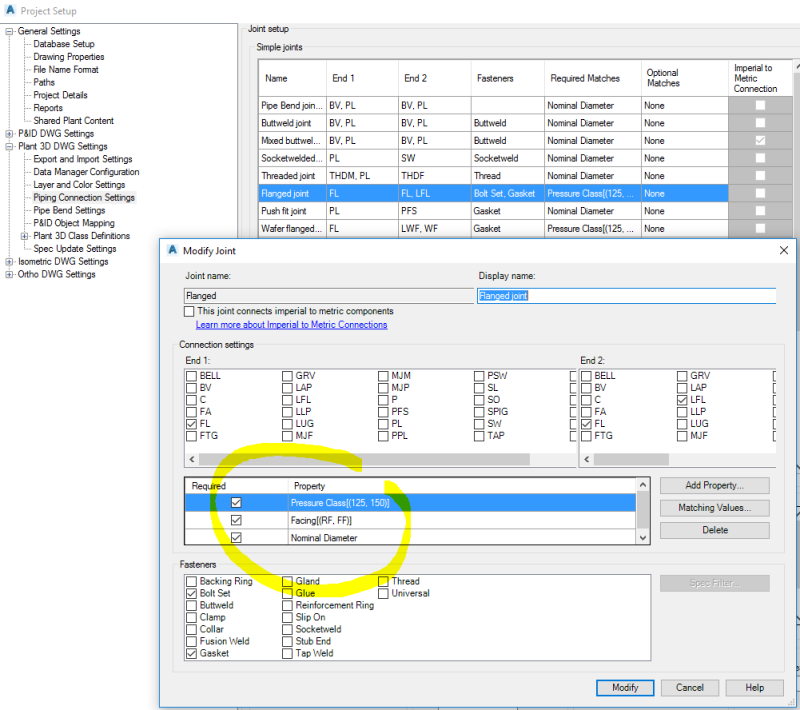
The modifications above will allow a flange with a FF facing and pressure class of 125 connect to a flange with an RF facing and pressure class of 150. But what about the connectors for this joint? One might assume that making the modifications above for the joint would extend to the connectors (in this case the Bolt Set and Gasket) however this isn’t the case. The connectors that are selected from the spec to complete this joint are found via separate filters that are only accessible by modifying the DefaultConnectorsConfig.xml file.
Just to be clear on what I am talking about, let’s assume that we have a simple spec with two flanges and a bolt set and gasket:
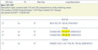
Notice that the only difference between the flanges is the pressure class and facing. Also, notice that the gasket and bolt are both 150 RF. What happens with this spec is that if we insert a 150 RF flange it will find and insert the gasket and bolt because their properties match that of the flange. However, if we insert a 125 FF flange it will end up putting placeholder connectors in the 3D model because the software will allow the connection to a 150 RF flange (due to the changes we made in Project Setup) but won’t find a corresponding bolt set and gasket with matching properties due to the fact that the XML file uses a separate filter for the connectors.
Let’s look at the DefaultConnectorsConfig.xml file after we have made the changes in Project Setup to the matching values for a “Flanged” joint. You can see the section highlighted in yellow below where the matching properties are defined (click on image to enlarge):
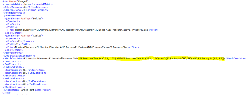
First thing you will want to notice is that the original match condition query for the joint (text colored to improve readability):
<MatchCondition>E1.NominalDiameter=E2.NominalDiameter AND E1.PressureClass = E2.PressureClass AND E1.Facing = E2.Facing</MatchCondition>
has been replaced with the new matching value query:
<MatchCondition>E1.NominalDiameter=E2.NominalDiameter AND (E1.PressureClass IN (‘125’, ‘150’) AND E2.PressureClass IN (‘125’, ‘150’)) AND (E1.Facing IN (‘RF’, ‘FF’) AND E2.Facing IN (‘RF’, ‘FF’))</MatchCondition>
As noted in the original post on this topic, this new query now restricts the “Flanged” joint to only allow connections for pressure classes which are either 125 or 150 and facings which are either RF or FF. Therefore, you need to modify the above match condition to read as follows if you want to allow any other flange connections (ex: 300 RF to 300 RF) in your project:
<MatchCondition>E1.NominalDiameter=E2.NominalDiameter AND ((E1.PressureClass IN (‘125’, ‘150’) AND E2.PressureClass IN (‘125’, ‘150’)) OR E1.PressureClass=E2.PressureClass) AND ((E1.Facing IN (‘RF’, ‘FF’) AND E2.Facing IN (‘RF’, ‘FF’)) OR E1.Facing=E2.Facing)</MatchCondition>
Reformatted to make this even simpler to read and understand:
<MatchCondition>
E1.NominalDiameter=E2.NominalDiameter AND
((E1.PressureClass IN (‘125’, ‘150’) AND E2.PressureClass IN (‘125’, ‘150’)) OR E1.PressureClass=E2.PressureClass) AND
((E1.Facing IN (‘RF’, ‘FF’) AND E2.Facing IN (‘RF’, ‘FF’)) OR E1.Facing=E2.Facing)
</MatchCondition>
Now that we have setup the desired match conditions for the two flanges, it it time to review the filters used for both the “BoltSet” and “Gasket”. From the image above you can see that these are looking for a match between the NominalDiameter, Facing and PressureClass for the bolt or gasket in the spec and E1 (the flange we are inserting) but not taking into account any that match with E2 (the flange that we are connecting to). To instruct the AutoCAD Plant 3D software to search for all gaskets and bolts which match the pressure class and facing for both flanges, we need to modify the XML file like so:
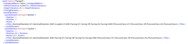
The new query will gather all of the gaskets and bolts from the spec that match the facing and pressure class of either of the flanged components (E1 and E2).
One last tip: be sure to keep this XML file stored safely within your template project (and maybe even create a backup copy of that). This is the same recommendation that we give for your isometric style configuration files because it is easy to accidentally overwrite the changes you have manually made by saving changes within Project Setup. Happy piping!