This week we want to share an article contributed by long-time AutoCAD Plant 3D evangelist and friend, Ian Matthew. This week Ian explains how AutoCAD Plant 3D calculates bolt lengths for standard flanged connections. Enjoy!
Introduction
Bolt sets are selected with the same criteria as gaskets, flanges, valves, etc. So pressure class, facing and size, influence the bolt diameter and bolt length.
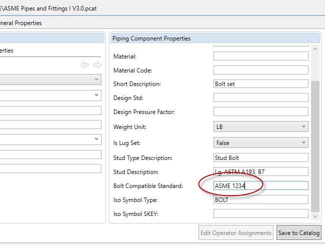
Bolt sets have a lot of properties similar to other components, especially port properties. You need a long description family, a short description, a standard and a bolt compatible standard. The isometric settings are plain and easy, you only have to have an Iso Symbol Type, as bolt sets aren’t drawn in the isometric drawing.
Defining Bolts
Bolts are placed in the catalog (usually the pipes and fittings catalog) and determine the selections that will be made. Having defined the bolt set, add it to the spec.
How are bolt sets selected? The selection is made by mating Nominal Size, Pressure Rating and Facing, so if you have 150lb RF flanges, then set those the same for your bolt lengths. That will determine if you use stud bolts, machine bolts….
Here’s an example from the CS150 spec:
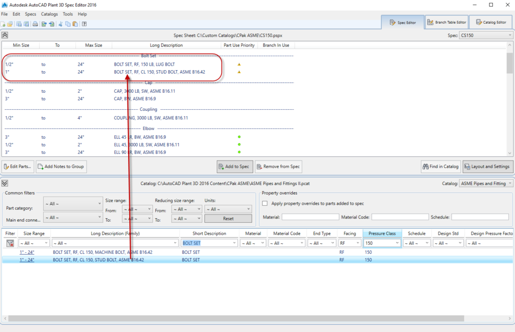
Here we have stud bolts for flange connections and lug bolts where the end type is LUG (as opposed to WF). We will look at connection compatibility later.
Looking closely at the Stud Bolt:
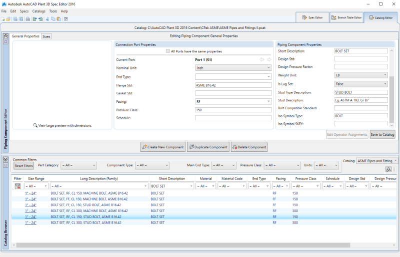
Notice the catalog item has the general properties tab and the sizes tab. The general properties tab is similar to that of valves and fittings. However, one property to note is “Is Lug Set”. This drives the bolt selection and length calculation differently. If The Lug Set is “True” then this bolt set will be used when the facing is LUG and a bolt set is used for each flange. If it is “False” then bolt connection calculations look through the connection and calculates based on mating flanges. If a wafer component (such as a Butterfly valve) is placed between flanges, then the bolt calculation recognizes the WF end type as a wafer and calculates the bolt lengths as the bolt length in the size properties (see below) and adds the face-to-face dimension for the wafer component plus an additional gasket thickness. (See more in calculating bolt lengths) later.
Bolt Lengths
When facings are the same and there are no wafer connections, then the bolt length is defined in the size tab for the bolt set. The sizes are the nominal diameter sizes and they determine the bolt size, the number of bolts needed to make the connection as well as the weight of the bolt set. Note that for the connection port properties, there is only one port and the only property that needs to be set is the nominal diameter. Here is an example for a 6”, 150#, RF stud bolt:
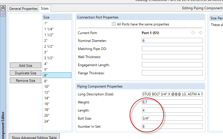
In this case the standard length is 4” and there are 8 bolt sets for each connection.
Long Description (Size)
If you look above, the long description for this bolt set is “STUD BOLT 3/4″ X @@@ LG, ASTM A193, B7 W/2 HEX. NUT 3/4″, ASTM A194, GR 2, 2 WASHER 3/4″, ASTM F436”. The “@@@” in the description is substituted in the final BOM with the calculated length of the bolt.
Bolt Length Calculations and Tables
When bolt lengths are calculated, the length is computed based on the wafer components face-to-face dimensions and the extra gaskets thicknesses and these values are added to the bolt length. In order to ensure that the final bolt length fits a standard length for ordering, a bolt length table is looked up and the next longest size is selected.
To see what bolt standards and standard sizes and lengths are used, go to the pull down menu Catalog and choose the option “Edit Bolt Length Mapping”.
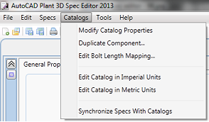
The following dialog appears:
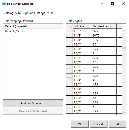
By default the length will round up to the value in this table.
However, you can override this table by creating a Bolt Standard Table:
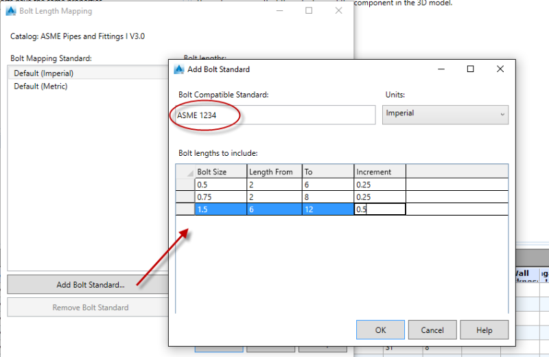
Enter the standard name and then the size table in the lower section. The table name MUST match the Bolt Compatible Standard in the General Properties of the bolt set. (Note in the above example only a few sizes are shown, but in real life ALL sizes must appear in this table):