As engineers, we always have to stay at the top of our game. Part of that arduous task means being the best Inventor user we can be. Sometimes, however, we don’t want to spend hours watching tutorials or learning how to do something new. That’s where we come in.
We’ve assembled ten tips and tricks that you may or may not know about that will help you improve how you use inventor and shave a little bit of time off of your design process. Most of the videos are under two minutes and you’re definitely going to learn something new. Find all ten tips and tricks below!
1. Stress Analysis Overview
Autodesk Inventor Stress Analysis environment contains tools to help you understand how parts and assemblies will react in various real-world conditions. This allows you to examine whether the assembly/part is overdesigned or if you might need to make some improvements to it’s loading characteristics. Through conversion studies, the final studies have maximized accuracy and minimal possibilities for error. Take a look at the quick tip video below to see how you might be able to utilize this tool in your design process.
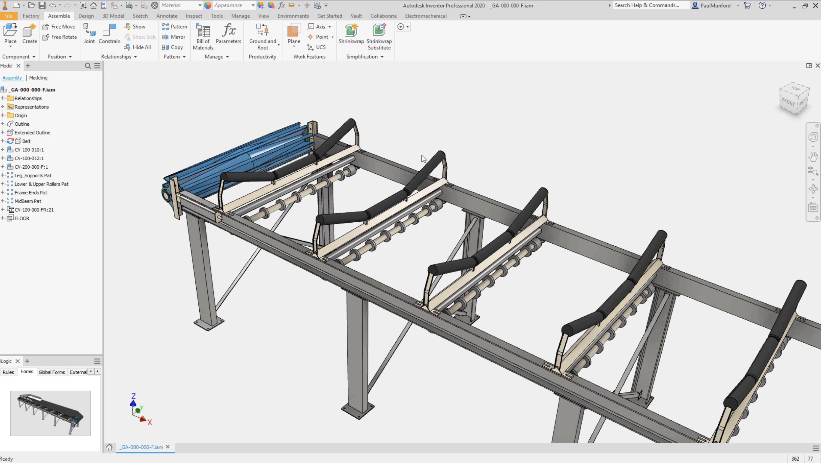
2. View Relationships Between Components
This video walks you through how to view the relationships between your components.
3. Custom Marking Menu
If you utilize Autodesk Inventor on a regular basis, it may interest you to customize the marking menu so what you use the most is literally right at your fingertips. There are, of course, preset marking menu options that Autodesk provides, but you also have the option to completely customize the menus to speed up your design process. Take a look at this quick and simple process in the quick tip video below!
4. Sheet Metal Rip Command
Utilizing the sheet metal rip command, you’ll be able to take a component design and “rip” it to easily create a flat panel from it that can be sent off to the cutter for manufacturing. By selecting the rip option under the sheet metal command, you’ll have several options on how you want to rip the model, point, point to point, or the entire extents of a face. Once you implement the rip utilizing one of these three options, with one more click of a button you’ll be able to transform your 3D sheet metal part into a flat pattern for manufacturing. Learn more about implementing the rip command in the quick tip video below!
5. iLogic
Autodesk Inventor has iLogic technology fully integrated within the software. It allows users to capture and invent engineering and product knowledge directly into virtual models. iLogic will simplify rules-based designs for any Inventor user. However, if you have a little programming experience, you can leverage iLogic as an even more powerful design tool. Take a look at how this powerful tool functions within Autodesk Inventor and see what it might be able to do for you in the quick tip video below!
6. Configurator 360 Overview
Creating a custom online product catalog has never been easier with Autodesk’s Configurator 360. It allows for full 3D viewing and customization control that allows customers or clients to request quotes, download files, and even generate 2D documentation with ease.
Starting in Inventor with Part or assembly design, you can set up all of your product parameters to interface with your catalog. After everything is set up properly, you’ll be able to export it to Configurator 360 with ease. Learn more about how this tool works in the Quick tip video below!
7. Tangent Constraint
Adding constraints to your designs within Autodesk Inventor is a crucial step in every assembly process. However, sometimes constraints aren’t as simple as just faces or centerlines. If you need a component to stay tangent to another part in your assembly, then the tangent constraint is exactly what you want to use. By some simple selections of tangent faces, you can assemble roller components, sliding components, and more. Watch the quick tip video below to master this tool.
8. Rotation Translation Constraint
Adding constraints to your designs within Autodesk Inventor is a crucial step in every assembly process. However, sometimes constraints aren’t as simple as just faces or centerlines. Take, for example, the need to have an unscrewing motion on a part. In the quick tip video below, we’ll walk you through how you might constrain a nut along a bolt so that it screws and unscrews just like it would in real life. Check it out below!
9. Re-Orient Imported Model
In this Autodesk Inventor quick tip, learn how to alter the orientation of a default model import.
10. Creating New Part Templates
In this Autodesk Inventor quick tip, we examine how to create new part templates – check out the short video below!
Written by:
Trevor English
Marketing Manager Trevor is an experienced marketing and content creation professional who has spent his entire career helping engineering technology companies reach their customers through digital media. He currently works for Autodesk on the Digital Acquisition Team where he’s responsible for social demand generation for the AutoCAD and Design and Manufacturing families. You can also see his written engineering marketing content on InterestingEngineering.com, Curiosity.com, and other sites across the web.
 Trevor is an experienced marketing and content creation professional who has spent his entire career helping engineering technology companies reach their customers through digital media. He currently works for Autodesk on the Digital Acquisition Team where he’s responsible for social demand generation for the AutoCAD and Design and Manufacturing families. You can also see his written engineering marketing content on InterestingEngineering.com, Curiosity.com, and other sites across the web.

Add comment
Connect with: Log in
There are no comments