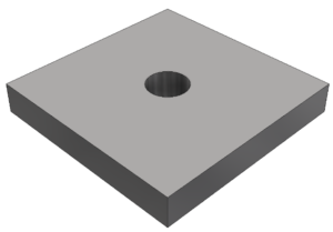
 If I gave you a model of a 50mm by 50mm by 6mm steel plate, with an M10 clearance hole through the middle of the face, and asked you to change the width of that plate – what should happen to the hole?
Using feature-based modelling we can decide how our model will change, this is known as ‘Design Intent’.
Click here to read part 01 in this blog post series for an introduction to Reliable part modelling.
Relationships
The key to creating complex models in Autodesk Inventor is maintaining control of relationships.
If you don’t understand the relationships you’ve built between parameters, sketches, features, bodies, parts constraints and assemblies – your model will not update in a predictable fashion.
The bad news is that Inventor won’t manage this for you (it can’t read your mind!).
The good news is that YOU have full control over this process.
Relationship rules 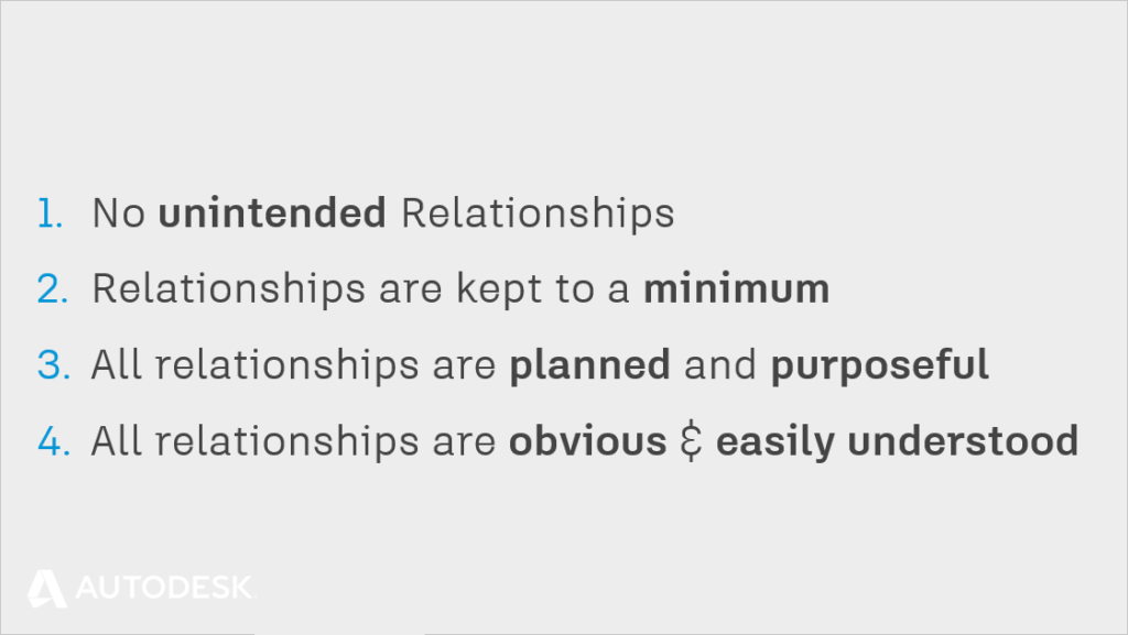
- No unintended Relationships
- Relationships are kept to a minimum
- All relationships are planned and purposeful
- All relationships are obvious and easily understood
Relationships, order of preference
Some relationships are more complicated for Inventor to work out than others. When you are planning your design intent, keep this in mind.
Create simple parametric relationships where you can, create complex feature to feature relationships only when you have too.
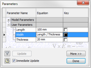
Parametric Relationships
Inventor is a computer programme. Computers are really, really good at Math. It may come as no surprise that the simplest relationship for Inventor to manage is a mathematical one.
Parameter1 Drives Sketch1 Geometry.
- Can you express a relationship in your design as an equation?
- Could you use iLogic to describe complex formulas?
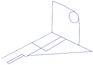
Sketch to Sketch
If you can’t express a relationship mathematically, and you need to express it geometrically, the safest way is to relate a sketch to another sketch.
This is known as a ‘Horizontal’ relationship – both sketches are on the same level. We are minimizing the number of feature relationships Inventor must calculate, and therefore reducing the opportunity for error.
Parameter1 Drives Sketch1 which drives Sketch2.
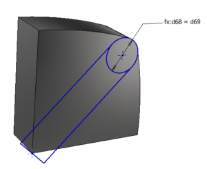
Sketch to Feature
Creating a sketch on the face of an existing feature is a common workflow. It’s not wrong to do this, but it’s worth recognising what you just did.
Parameter Drives Sketch1 which drives Feature1 which drives Sketch2.
We have now created a far more complex sequence of events which Inventor must calculate to get a result.
Powerful, certainly, but frustrating if we unintentionally created a relationship we weren’t aware of.
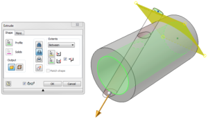
Feature to Feature
Feature to feature relationships are the most complicated relationships for Inventor to calculate, because it must calculate two ‘branches’ of features before it can compare the two branches to get a result.
These Feature to Feature relationships can be the trickiest type of relationship to edit parametrically, because you must make sure that all the contributing features make sense in order for the final feature to make sense.
Parameter Drives Sketch1 which drives Feature1 which drives Sketch3 which drives feature 3.
Parameter2 Drives Sketch2 which drives Feature2 which also drives Feature 3
Planning design intent
If you are going to spend even a day modelling a design, it’s worth spending 20 minutes thinking about it before you start.
Back in the mad, bad old days of 2D CAD we were more productive when we mashed the keys quicker. This approach won’t reward you when creating parametric part models.
Productivity in Inventor is more like playing chess. Thinking about your design intent, and planning ahead will help you to create more stable, more useful, more reliable part models – which will reward you and your colleagues for the duration of your project.
Preparation | Reliable Part Modelling 03
This blog post is based on an Autodesk University class, by Luke Mihelcic and Paul Munford. You can watch a recording of the class, and download a handout that goes with this presentation from the Autodesk University website here:
MFG226705: Reliable Modeling Techniques for Complex Part Design in Inventor
Edit 2020/11/24
This class was updated and repeated for Autodesk University 2020. You can find the revised version of the class, with video, handout, and dataset here:
‘Reliable Modeling Techniques for Complex Part Design in Inventor’ At AU2020
We also created a second part to the class: ‘Reliable Techniques for Complex Assembly Design in Inventor‘ – Here’s the link:
‘Reliable Techniques for Complex Assembly Design in Inventor’ at AU2020


Thanks for this series! Can't wait to keep reading, but I just wanted to drop a quick note about the link to the next section; it still reads as "(Coming soon!)". Cheers!
Thanks Ethan - we fixed it :)