In this post we will learn how we can add documentation to our models to aid communication of our design intent to our colleagues.
Don’t forget – it could be you who opens this design in three months’ time and has to figure out how to make a change!
Parameter comments
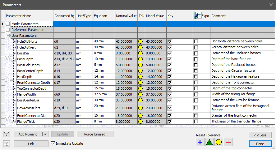
The first thing we want anyone to do upon opening our model – is to open the parameters manager and look for useful parameters.
If we have created a named parameter called ‘Length’ and our colleague wants to change the length of the component – the design intent is obvious. Your colleague will thank you for making their life so easy!
It’s often not possible to capture the entire design intent in a parameter name, so add a comment to clarify what the parameter is controlling.
Tip: Create user parameters that capture your design intent before you model anything. If you can’t think of them all up front, don’t worry – just come back and add more user parameters as you need them.
If you want to keep track of a parameter (for example, in an equation), but it won’t be a driving parameter. Use the ‘Parameter name = Parameter value’ formula to rename parameters as you go along.
Communication by Adding Notes
The more information you can embed in your design, the more likely that your colleagues will be able to figure out your design intent.
Maybe you want to leave a note in your file to say:
‘I’m not finished with this model yet!’
Or
‘Use the imbedded iLogic form to edit this model’
We have several options available. I suggest that you discuss this with your team and pick one that everyone can use consistently.
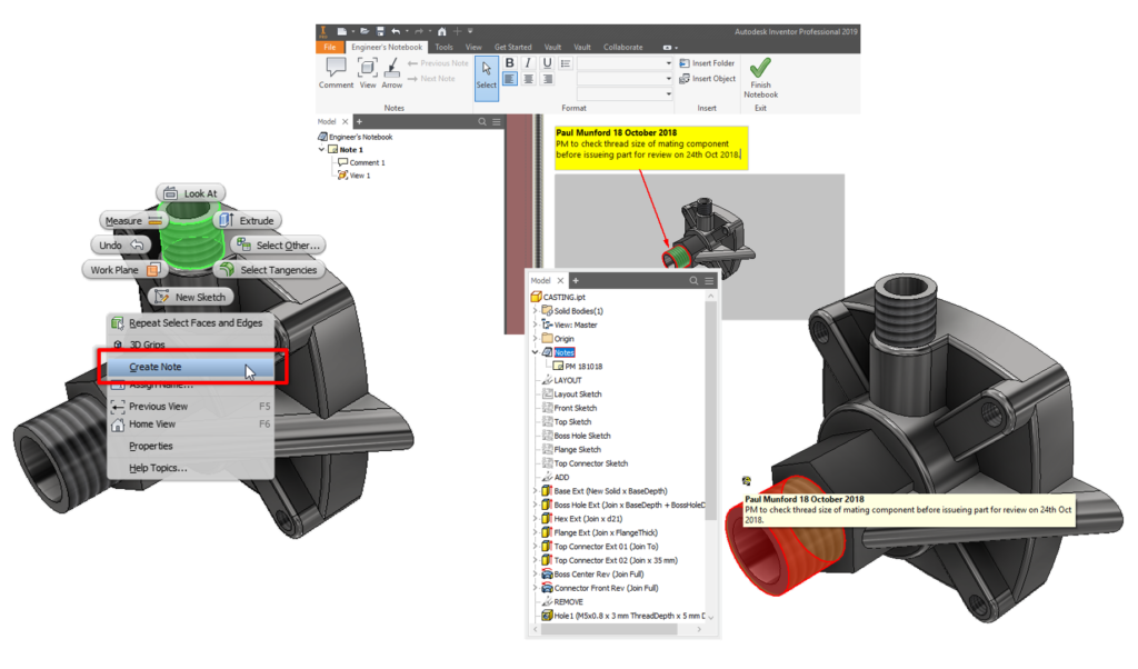
Engineers Notebook
Right click on any part file in an assembly, or any sketch edge of feature in a part file and pick ‘Create Note’ from the context menu.
You will automatically be taken to the Engineers notebook, where you will find a screenshot of your component, and a text note for you to add your information to.
More information in the online help:
https://help.autodesk.com/view/INVNTOR/2019/ENU/?guid=GUID-19FA6297-F980-456D-A53F-226DA9870B73
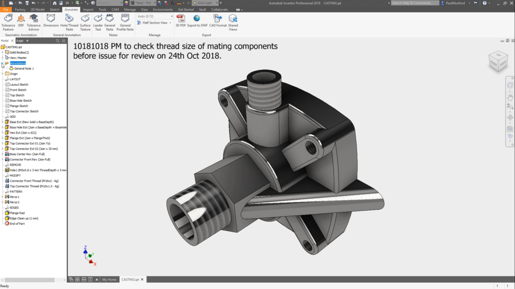
Model based Annotation – General note
Model based annotation is relatively new. If you haven’t tried it out yet – give it a go.
My favourite is the ‘General Note’ tool, which creates a note which sits in the corner of your screen and remains there – even if you rotate the model.
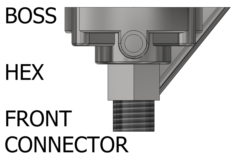
Sketch notes
It’s old school – but it works. Leave a note by adding text in your sketches to help your colleagues understand your design intent. For example, you could label your features:
iLogic forms to communication of design intent
Even if you take the time to name and comment your key parameters, it can be confusing for your colleagues to trigger the change they need.
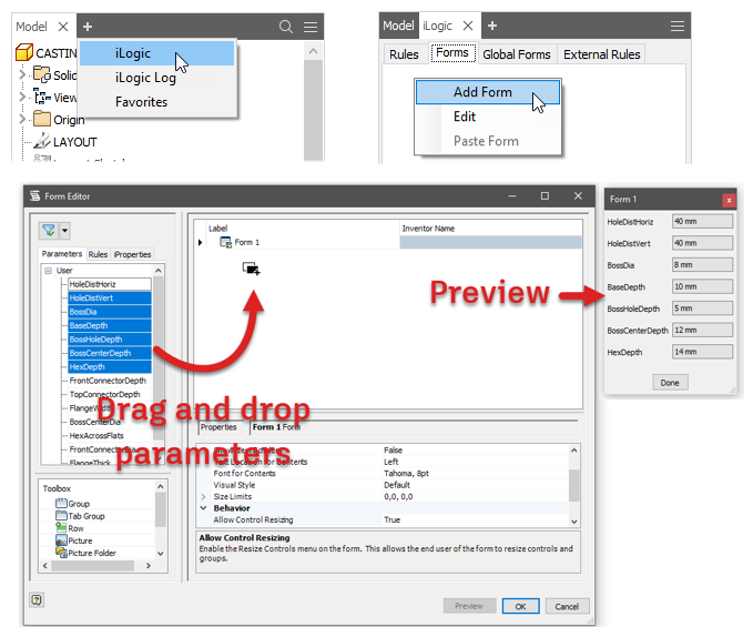
A really simple way to communicate design intent is to use an iLogic form to control the part.
- Open the iLogic browser
- Create an iLogic form
- Drag and drop parameters
- Click on the button to trigger the form.
iLogic form pro-tips
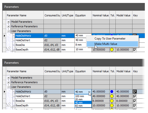
Limit choice to the available sizes by making parameter multi value.
Edit the name of your form. The name of your form can be seen on the button that triggers your form to appear.
Edit the control type to ‘slider’. A slider control has minimum, maximum and increment properties. This will limit users from picking a value which is out of range.
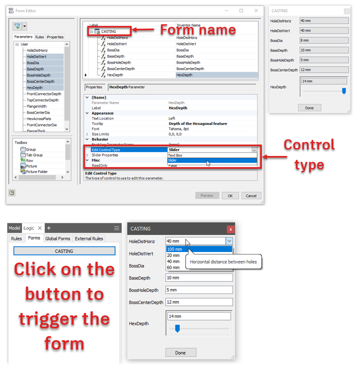
Note: Your parameter comments become tooltips – no effort is wasted!
Reliable part modelling conclusion
Parametric modelling with design intent in mind isn’t easy. It requires thought, planning, preparation, testing and good communication.
But – you read this far, so I’m guessing that you are the sort of problem who likes a puzzle and loves a challenge!
I hope that you have found this information useful. Let me know how you apply it to the projects in your company.
Introduction | Reliable Part Modelling 01
Have you found this series useful? Click here to read part 01 in this series for an introduction to reliable part modelling.
This blog post is based on an Autodesk University class, by Luke Mihelcic and Paul Munford. You can watch a recording of the class, and download a handout that goes with this presentation from the Autodesk University website here:
MFG226705: Reliable Modeling Techniques for Complex Part Design in Inventor
Edit 2020/11/24
This class was updated and repeated for Autodesk University 2020. You can find the revised version of the class, with video, handout, and dataset here:
‘Reliable Modeling Techniques for Complex Part Design in Inventor’ At AU2020
We also created a second part to the class: ‘Reliable Techniques for Complex Assembly Design in Inventor‘ – Here’s the link:
‘Reliable Techniques for Complex Assembly Design in Inventor’ at AU2020


Sir, I want to go to class, is that possible?
Hi Randa, This has already happened - please click the link to watch the class recording and download the handout! https://www.autodesk.com/autodesk-university/class/Reliable-Modeling-Techniques-Complex-Part-Design-Inventor-2018 Thanks Very much! Paul