There isn’t a game series more iconic than the Legend of Zelda, and with each of these comes the constant upgrading of swords until you reach the greatest blade of all time; the Master Sword. But have you ever asked yourself if it is really smart to upgrade? Sure, it does 2 times the damage of the white sword, but does that mean it is just as strong? Here we take a look to see if the simple design of the Wood and White sword hold up better in a tensile test versus the fancy looking Magical Sword.
To begin, we start out in Fusion 360. Since it looks cool, I’ve modeled the 3D version of each sword, but to help keep the analysis simple we really only need the 2D sketches. If you’ve downloaded the 3D swords from the Fusion Gallery, all you have to do is start a new sketch and choose to project each surface. From there, export a .dxf file and you’re ready for Autodesk Simulation Mechanical.
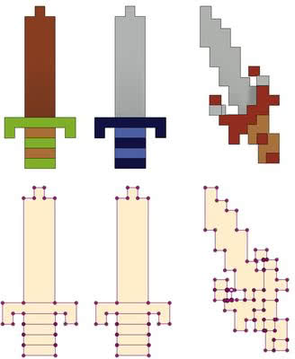
Much like finding the Magical Sword, getting the .dxf file into Simulation Mechanical is no easy task. To start, when choosing a file to open change the file type to DXF. This will activate the hidden Options button (much like burning a bush to find a stairway). In the options dialog you must come up with the combination that will import your sketch lines into the YZ (or 2D) plane. After doing this, you will be ready to continue your quest.

Your lines will import as shown below. To 2D mesh the swords, each part will need to consist of a single region. To make this easier, you should start by deleting 2 of the swords and just analyzing 1 at a time. You will also have to delete the lines making up the separate sections of the hilt.
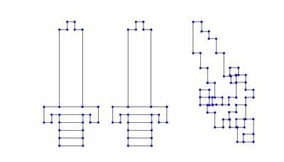
After deleting the necessary lines, you’ll see that you are left with a sword that has missing lines! To complete the sketch, double click on Plane 2
<YZ(+X)> and draw in the necessary lines. Please note that they will be construction lines at this point, and will have to be drawn on the same part number as the rest of the lines (in this case, part 255). With this done, you’re then ready to mesh your model.
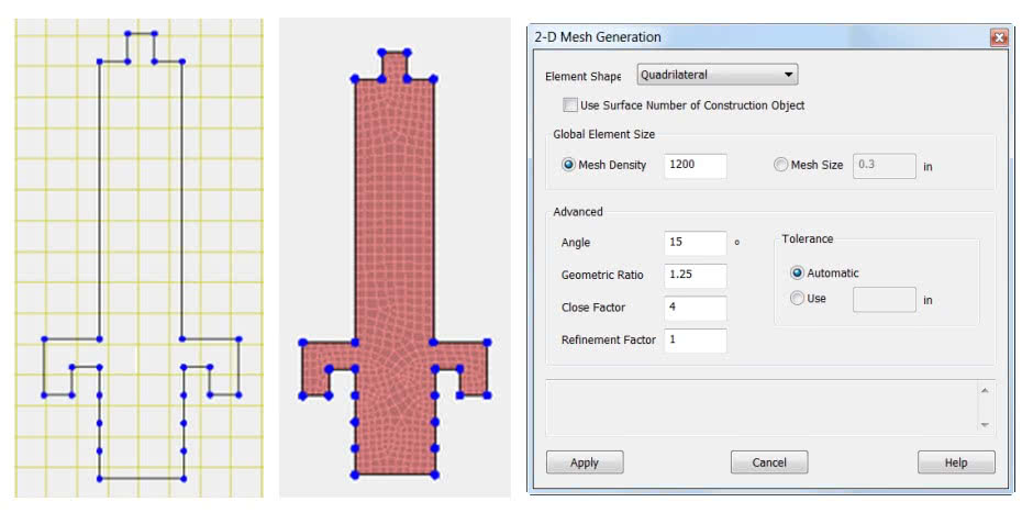
To mesh the model, right click on the sketch line heading (1<YZ(+X)) under part 255 and choose Generate 2D Mesh. I have increased the Mesh Density to provide more accurate results. You can then apply the material for each sword. I used a custom wood material, steel and titanium for the 3 swords.
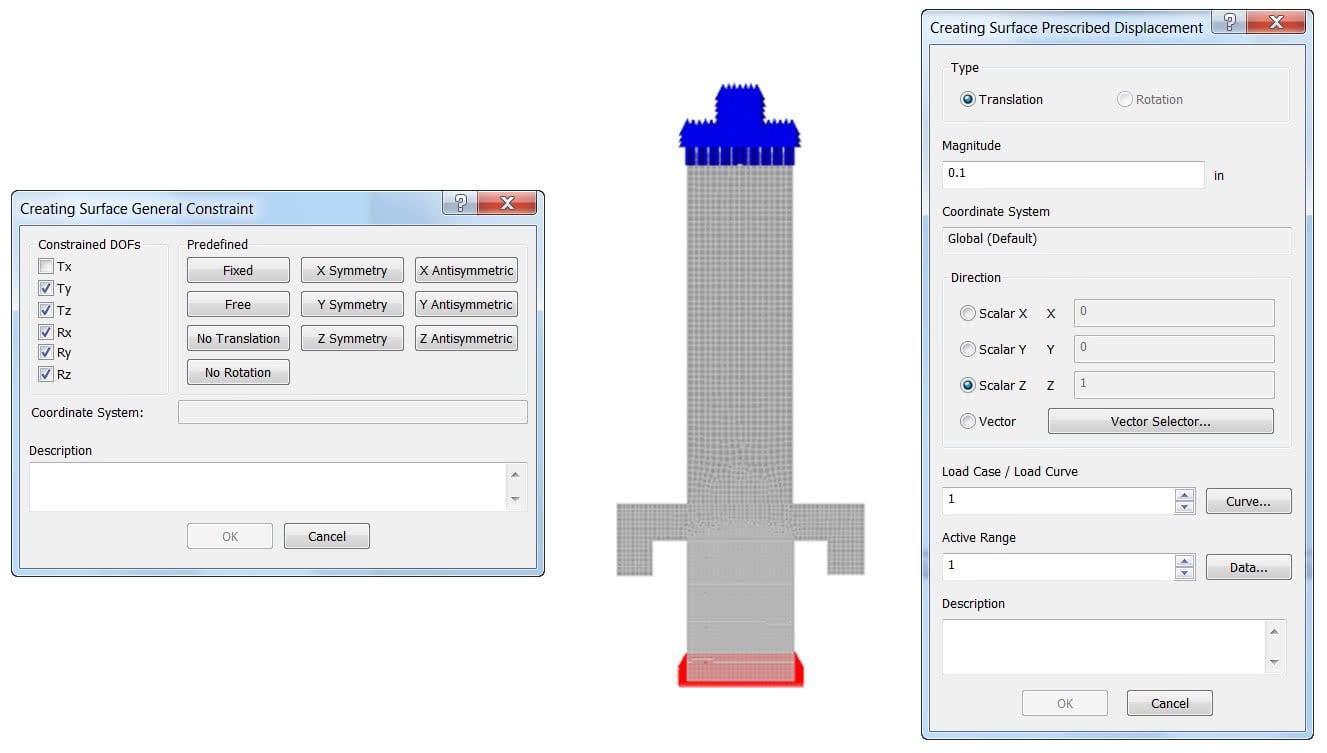
After meshing, select the nodes at the bottom of the hilt and apply a General Constraint, fixing all degrees of freedom other than Tx. You can then select the nodes at the top of the sword and apply a prescribed displacement of 0.1 inches. This will be applied over 1 second. You’re now set to run a tensile test!
By showing the factor of safety, we see that the White Sword does outlast the Wood Sword, but the fancy geometry of Magical Sword causes hot stress risers, causing it to fail before the White Sword. Perhaps Link should think twice before trading up.

(0)