Finite element analysis is an invaluable tool for predicting structural behavior and performance of components. However, as with any numerical simulation tool, it does have its limitations. One of these limitations is that, at least without a good bit of user intervention, it assumes nominal, continuous distributions of material properties throughout a given part. This is typically valid for metal structures and even continuous fiber ply layups, but what about fiber-reinforced injection molded plastics?
When a part is injection molded, separate melt flows meet up to form weaker seams, known as weld lines. The weakness is a result of the fiber chains not entangling properly across the seam, as shown in Figure 1. Standard finite element modeling does not account for this phenomenon (again, not without user intervention and possibly faulty assumptions).
Figure 1. Weld line formation in an injection molded part
However, Moldflow Insight from Autodesk does calculate the final distributions of the weld lines, which can then be fed to Helius PFA. Helius PFA then integrates with standard finite element tools, such as Nastran In-CAD, for more accurate, as-manufactured stress analyses. Not only that, Helius PFA (the PFA stands for Progressive Failure Analysis) is able to determine post-fracture behavior of the structure, once ultimate failure occurs. See Figures 2 through 4 for illustrations of these phenomena. Note that, due to the weld line, the seat breaks in a location we never would have predicted if we had used standard FEA!
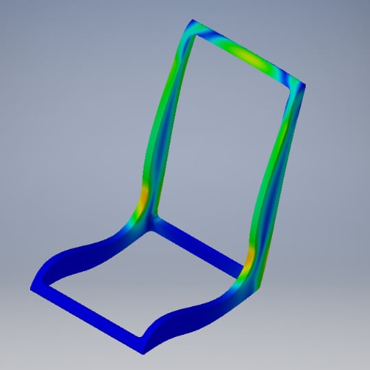
Figure 2. Stresses based on nominal material property distributions

Figure 3. Weld line effect calculated by Helius PFA using Moldflow Insight
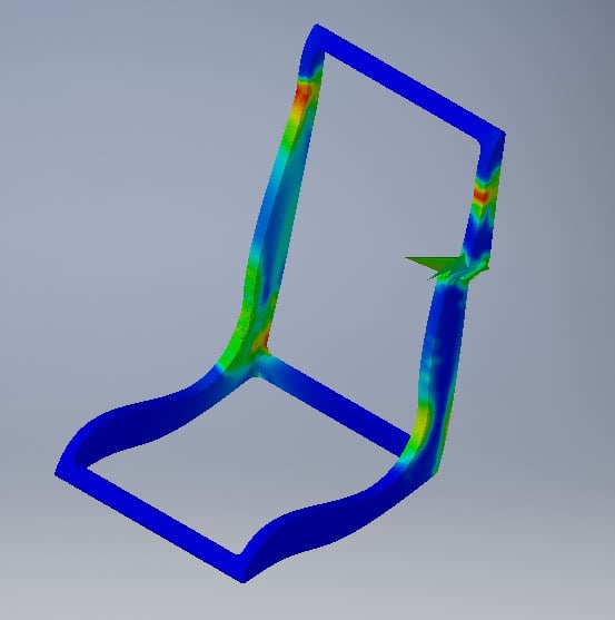
Figure 4. Post-fracture behavior calculated by Helius PFA, postprocessed in Nastran In-CAD
By taking advantage of Autodesk’s selection of simulation tools, manufacturers can much more accurately determine the integrity of injection molded components.

(0)