Article by Clinton Perry, PowerMill Product Marketing Manager
It’s that time of year again. The Autodesk PowerMill development team has just released the latest update to Autodesk’s CAM software. Following recent releases, this specific update includes a healthy mix of fixes, improvements, and new capabilities aimed at simplifying the daily life of CAM programmers around the world.
PowerMill 2022 – Customer Release: May 12, 2021
In this blog, we’ll provide a brief overview of the major highlights as well as offering links for those that want to learn more.
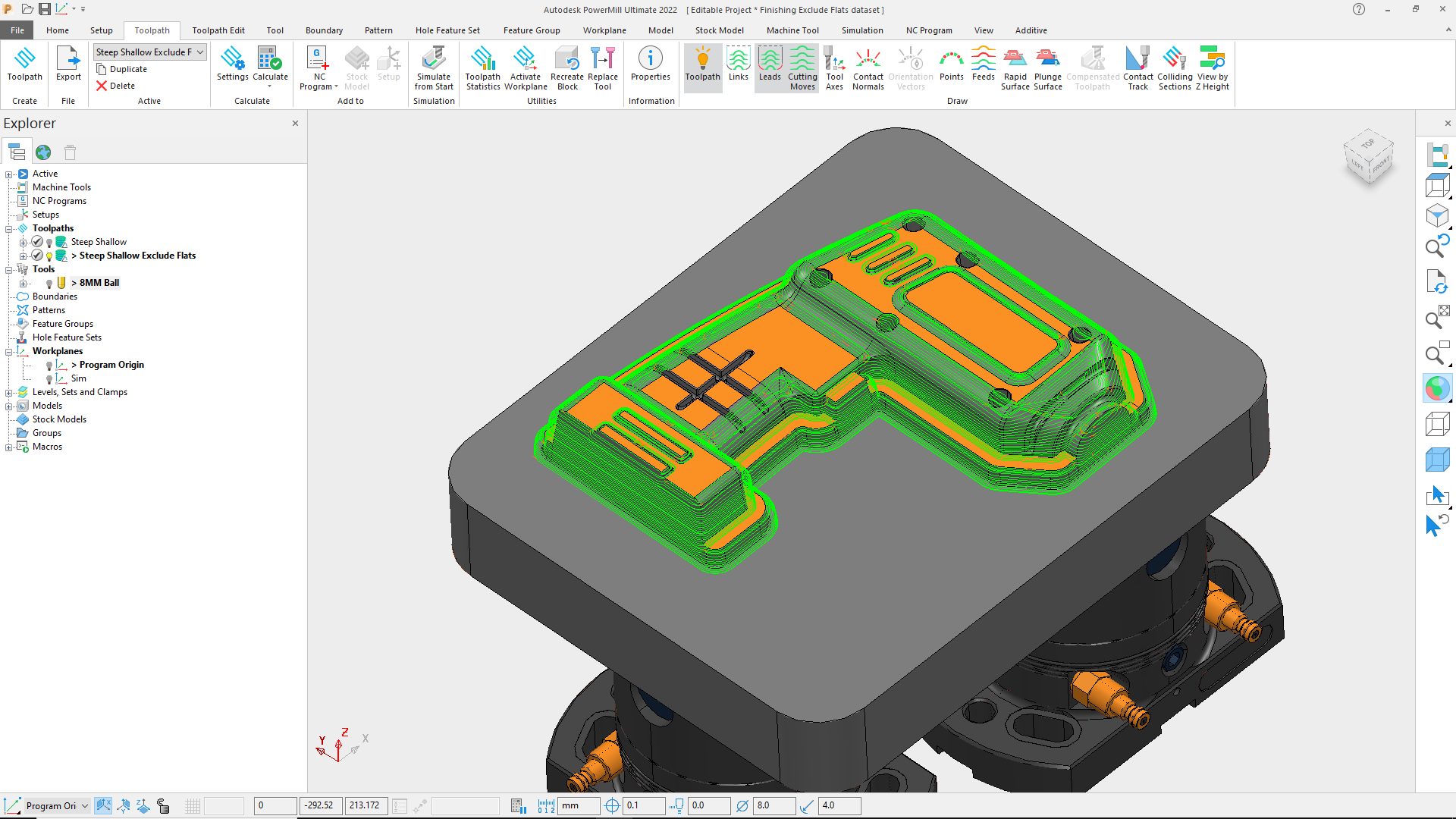
Finishing toolpaths now exclude flat areas
We’ll kick things off with a pretty neat improvement to some of PowerMill’s most commonly used finishing toolpaths (Steep & Shallow, Raster, and 3D Offset Finishing) to simplify the programming of parts containing flat/planar areas. PowerMill 2022 includes a new option to exclude flat areas during toolpath calculation. This small, but significant, update means programmers no longer need to spend time creating separate boundaries to limit the machining. Instead, PowerMill simply calculates a toolpath with the flat areas removed – simple!

But why is this such a big deal?
Well, it won’t surprise you to know that the vast majority of parts programmed with PowerMill consist of a mixture of doubly-curved surfaces, angled faces, and flat/planar regions. Generally speaking, the doubly-curved surfaces are best machined with spherical cutting tools (e.g. ball nose, tapered spherical, and so on) using a small stepover to achieve the desired surface finish. By comparison, the flat areas are best machined using flat-bottomed cutting tools (end mills, tip radiused end mills, and the like) with the tool axis aligned perpendicular to the flat face that’s being machined. This allows the use of larger stepovers that can produce an acceptable finish in less time than would be possible if a ball nose cutting tool was run with a smaller stepover. The ability to automatically split the model into steep, shallow and flat areas further simplifies the CAM programming of complex, feature-rich components.
From usage analysis, we know that these three finishing strategies are some of the most commonly used toolpaths inside PowerMill – and so this improvement should result in a lot of PowerMill users saving time and effort.
More accurate flat finishing
In our previous update, we discussed excluding flat areas from Steep & Shallow toolpaths – but these areas still need to be machined. In most cases, this is best achieved using a Flat Finishing toolpath (either Raster or 3D Offset). And it is here, where we see the next improvement in PowerMill 2022 – namely improved toolpath accuracy. In previous releases of PowerMill, there were occasions where the toolpath could contain chamfers in internal corners. These small errors could result in material being left un-machined which would need to be removed later – either using additional toolpaths or by manual polishing. This latest release of PowerMill now produces more accurate toolpaths – reducing the risk of material being left un-machined and helping to avoid the need for manual polishing.
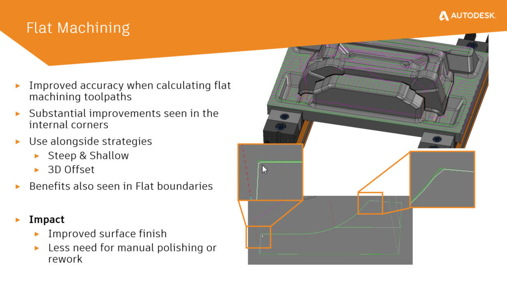
As the underlying code is used in other areas of PowerMill, such as the previously mentioned Steep & Shallow, Raster, and 3D Offset finishing toolpaths, these and other features will also see improved accuracy.
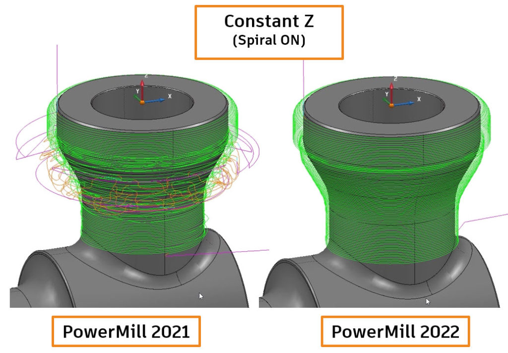
Constant Z with Undercuts
Some releases ago, PowerMill’s Constant Z finishing toolpath type was updated to allow it to handle parts containing undercuts. In these cases, it was possible to machine the undercut either, a) using a lollipop or disk cutting tool (great if you only have a 3-axis machine tool), or b) by using PowerMill’s automatic 5-axis collision avoidance.
When using the automatic collision avoidance option, there were, unfortunately, rare occasions when a toolpath would be processed that was either incomplete or fragmented. This could result in additional toolpaths being required or even parts needing additional, manual polishing. With this latest release of PowerMill 2022, toolpath quality is greatly improved – as we can see if we compare the processing of this simple lug on an oil and gas part. In this case, the part is being machined with a Constant Z toolpath with “Spiral” switched on and the automatic collision avoidance activated. Note how, in previous releases, the toolpath suffers from excessive fragmentation, whereas the toolpath produced by PowerMill 2022 is complete – containing a single, smooth toolpath segment.
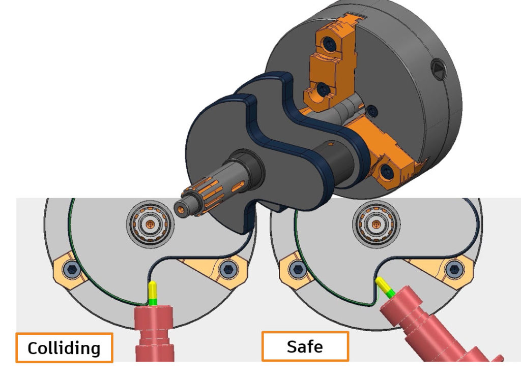
4-axis and Rotary with Automatic Collision Avoidance
Continuing the theme of automatic collision avoidance, this powerful option really has transformed 5-axis programming inside PowerMill. Customer feedback has been so positive that the development team decided to extend this same functionality to work with 4-axis and Rotary finishing toolpaths.
These toolpaths now include the option to define clearance values that will be used to tilt the 4th axis of the machine to avoid any collisions that might occur between the cutting tool assembly and the workpiece. In order to produce NC programs containing 4-axis motion only (for both cutting and non-cutting connection moves), it is also possible to define tool-axis limits that will constrain the toolpath. This ensures the resulting post-processed G-code file will only contain 4-axis commands – and not output any 5-axis movements that could cause the CNC machine tool any problems or trigger any alarms.
Projection Ranges
If you’ve ever used PowerMill’s various projection toolpath types, the chances are you’ve experienced this problem first hand. You’re trying to machine a particularly complex component and have decided to use Projection Finishing toolpath (either Curve Projection or Surface Projection) combined with a 3D surface that you produced using Autodesk Fusion 360 or Autodesk PowerShape. You’ve created a surface that will be used to control the shape and extent of machining – ensuring you cut the part exactly how you want. Unfortunately, when you calculate the toolpath, you see that it is machining up and onto the fixture that secures the part in place. Fortunately, you know that PowerMill can fix this by ignoring the fixture – so you simply re-calculate the toolpath – but this time remembering to tell PowerMill to ignore the fixture model. Great, that’s simple, right?
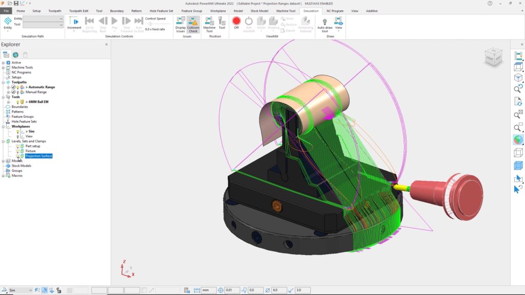
The image below shows a typical example of a component being machined with Surface Projection finishing. Here we can see the reference surface (shaded in cream) and the resulting projection toolpath over-machining the fixture.
Now imagine if the projection toolpath wasn’t just projecting onto the fixture, but was also projecting onto neighbouring parts of the model that you DO actually need to machine. You can’t just tell PowerMill to ignore that surface – as it needs to be machined! So how can you create the right toolpath?
This is where Projection Ranges can help. As the name suggests, these options allow you to define the distance that the projection toolpath is allowed to project away from the reference surface being used. A new option in the toolpath settings menu allows you to define both minimum and maximum projection range distances (for Curve and/or Surface Projection Finishing toolpaths). These will then be used to control the extents of the toolpath and prevent it from projecting onto neighbouring faces of the part (or the surrounding fixture).
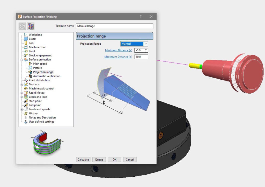
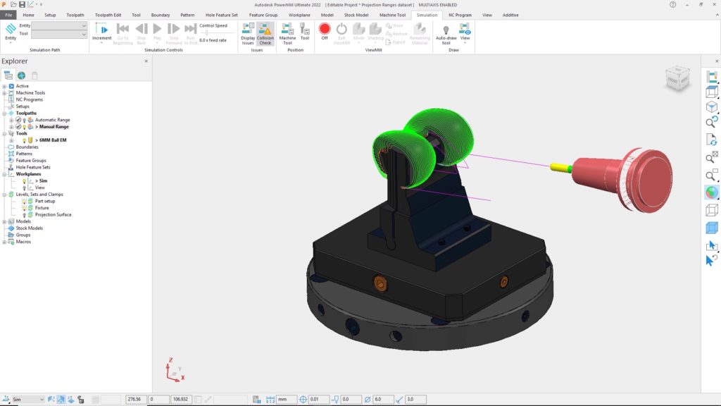
While Projection Ranges were available in previous releases of PowerMill, they were only accessible using typed commands. The release of PowerMill 2022 sees these options being added to the toolpath settings form – making them even easier to find and use. The image below shows our previous example toolpath re-calculated with suitable projection range values. Note the over-machining has been removed.
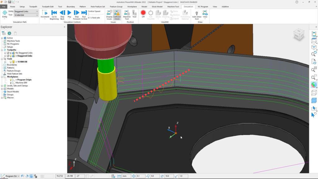
Staggered Start Points
The final major highlight we’ll include here relates to a new feature to allow start points on toolpaths to be staggered. This feature (which only applies to closed toolpath segments) automatically moves the start position of toolpath segments to improve machine motion, resulting in a better surface finish.
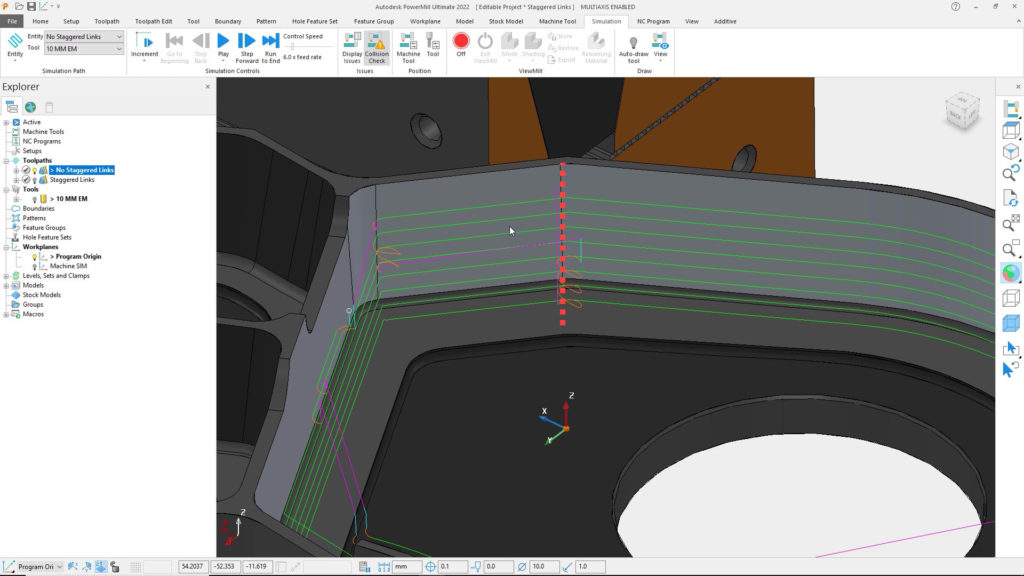
In this example, we’re using Swarf Finishing to machine the tapered sidewall of a part with the side of the cutting tool. Note that, by default, the toolpath start/end points are all aligned vertically (highlighted by the dotted red line). When this program is run on the machine the cutting tool will have to slow down at the end of one of the passes. It will then change direction to lead out of the material, move over to start the next lead-in move, before engaging into stock and continuing to machine the part. This movement is likely to leave a dwell mark on the component – partly due to the changing cutting forces but also the risk of one or more machine axes having to reverse direction.
It is possible to minimize the possible dwell mark by using arc lead in/out moves. However, by staggering the toolpath start points, it is possible to do an even better job. Staggering the points creates additional space between the end of one toolpath segment and the beginning of the next. This additional space helps maintain the forward motion of the machine tool, removing the need for the machine to reverse direction. This can have a positive impact on surface finish and machining cycle time – as the machine doesn’t have to slow down and speed up again.
If we apply staggered start points to our previous example, we can see a subtle but important change. The connection moves are staggered relative to each other (highlighted with a red line).
The use of staggered start points has an additional impact as each toolpath segment will, effectively, clean-up any witness line left by the preceding pass – further improving surface finish.
So that’s it. The top 6 improvements in PowerMill 2022. If you’d like to read about every fix and improvement, check out the official release notes at https://help.autodesk.com/view/PWRM/2022/ENU/
Want to learn more?
If you want to take a deeper dive into this release, why not watch this 30min release highlights.
Ready to download PowerMill 2022?
Existing customers
PowerMill 2022 will be released to customers starting May 12, 2021.
Eligible customers with an active subscription or maintenance agreement will be able to download the latest release starting May 12, 2021. Customers can download using the Autodesk Desktop App or by logging into their Autodesk Account. Alternatively, visit our Services Marketplace to contact your local Autodesk team and discuss your specific business needs.
New to PowerMill? Why not try a free evaluation
New to PowerMill and want to see how it can help you solve your toughest CNC machining challenges? Contact our team of manufacturing specialists at www.autodesk.com/powermill-evaluation to learn more. Submit your contact details and our team will contact you to discuss how Autodesk can help your business to be more successful.


Add comment
Connect with: Log in
There are no comments