In this blog, we’ll be working through some of the basics of 3D Sketch: Forma’s powerful modeling mode that enables the creation and modification of complex shapes. We’ll also quickly learn how to leverage this tool to design cantilevered buildings featuring various unique angles.
The chosen site for our demonstration is located in downtown Denver, Colorado, a stunning city, nestled at the face of the Rocky Mountains and blessed with ample sunshine year-round. Our site is situated at the intersection of several city districts, offering numerous opportunities. The surrounding districts include the Downtown Core with its rotated grid, the Performing Arts District, the Auraria Campus, the Entertainment District, and the picturesque Cherry Creek waterway that cuts through the area.
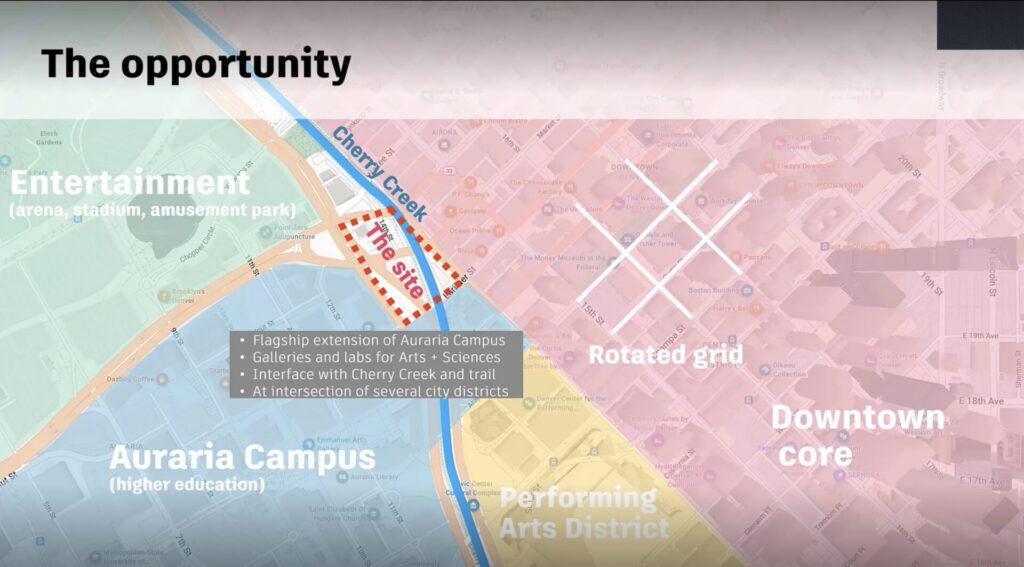
In this demonstration, we’ll design a flagship extension to the Auraria Campus complete with some hypothetical galleries and labs. The site we will be utilizing for this project consists of three portions of land, two triangular and one rectangular, which are currently being used as parking lots.
Let’s begin the first phase of our demonstration by working on the two triangular portions of the site. Our design inspiration comes from the remarkable Denver Art Museum, designed by Daniel Libeskind, that cantilevers over the street with some incredible angles.
Now that we’ve set the stage let’s start 3D sketching!
Once we’ve launched 3D Sketch, we can start by making “Primitives”. These primitives are a nice starting point as they are immediately watertight, with no geometry issues. Primitives include cubes, pyramids, roofs, cylinders, and domes. We can start by creating a cube on one of the triangular portions.
Initially, by default, the cube aligns with the world north. However, we have the option to modify this alignment by navigating to the “Set Axes” option in the “Guides and Measurements” menu. Given this modification will have an impact on the alignment of every structure created at future stages, it is recommended to set the axis widget based on the most suitable angle for the project. For this site, we’ll be using a surrounding building, so that our cube aligns with the axes of the buildings in the vicinity.
Additionally, we can group this cube by right-clicking on it. Grouping allows us to manipulate that particular geometry without affecting the rest of the design. The cube becomes a container with its own local access, initially aligned with the world axis. However, this alignment can be adjusted through the “Set Local Axes” option in the same “Guides and Measurements” menu.
We can easily extend this primitive cube by clicking on a face and hitting the “Extrude Face” option. By repeating this action, we’ll have a nice rectangular block. Given it is a triangular site, let’s grab the edges and use the “Move” tool to move it inwards and create an angular shape. The dimensions for this adjustment can also be manually entered. Pressing the shift key, lets us lock on to the intuitive red axis that shows up on the screen providing us with a guide to work with. Considering the site slopes down a bit, we can also Extrude the bottom face to ensure that it meets the ground at both ends.
Harnessing the power of Instances
“Instances” are a powerful tool that can be leveraged to save time and ensure consistency while creating identical objects. Instances enable modifications made to one object to automatically apply to any copies. To achieve this, we can copy (CTRL C + CTRL V for Windows and CMD C + CMD V for Mac) the angular structure onto the second triangular portion of the site. Since these two buildings are identical, they become Instances of each other. Double clicking on one building and selecting the top face highlights the top faces of both buildings. Similarly, making any changes in one building would be automatically applied to the other, using this impressive tool.
Using the “Rotate” command, you can either type in the angle of rotation or move the widget to somewhere meaningful and use the arrows to rotate the structure by eye. In this case, we rotate the second building to align its edges with the Creek, just like the other building.
Adding angles and cantilevered edges
Now we have two identical triangular buildings, with space for maybe some service parking near one and some gardens adjacent to the other. The next step would be to cantilever the walls and to give the roof some angles. We have two approaches to achieve this: the “Tilt Face tool” and the “Move tool”.
The Tilt Face tool, accessible through the contextual toolbar or the T F shortcut, is incredibly powerful. It allows us to tilt edges while keeping the face planar and the adjacent walls vertical. This tool’s widget consists of a few important components. The first component is the grip with no dimensions on it, and it can be used to identify the roof line from where the structure will pivot. This edge will remain at its current elevation. The part of the widget with the arrows and the dimension box should be placed where we want to actually tilt the roof. By utilizing this tool, we can achieve a tilted face while keeping the surrounding faces vertical, making it a highly resourceful tool for any plan.
The next course of action would be to move more edges and to cantilever the walls. We can select the edges of our choice and use the Move tool (or press the M key) to create some unique angles. Due to the various angles involved, the world axes might not be as helpful, but the 3D Sketch tool provides a temporary perpendicular axis from the selected edge, serving as a useful guide.
When using the Move tool, non-planar faces may be created, but they will appear smooth until hovered over. By right-clicking on the dashed edge, we can choose “Facet Smooth Faces”, which separates the facets into independent triangular faces. This action can be reversed by selecting the “Smooth Selected Edge” option.
Leveraging the diagnostic capabilities
3D Sketch allows us to modify individual parts of any solid structure, while its diagnostic capabilities help us avoid errors along the way. The default diagnostics enabled indicates if the building that we’ve created is completely watertight. For instance, if we were to delete the top edge of the solid, we would see some planes turning red as the building would no longer be watertight.
With that, we now have two buildings featuring intriguing cantilevers, reminiscent of the Denver Art Museum. These structures could serve as either hypothetical auditoriums or galleries for the campus.
Stay tuned for part two of this blog, where we will delve further into leveraging the 3D Sketching tool from Autodesk Forma to create unique and captivating designs effortlessly.