3 Tips To Mastering Parameters
Tips & Tricks
Creating sketches is a fundamental part of modeling and with every sketch comes many parameters, equations and often construction geometry. Here are a few tips that will help you organize your parameters. Let Inventor do the math for you and use reference dimensions to help remove additional construction geometry. Even if you’re an advanced Inventor user you may not be aware of one or more of these tips and could find value in using them quite often.
Naming Parameters on the fly
Have you ever needed to edit parameters and upon launching the Parameters dialog see a bunch of “D” parameters? We have all been there and it is a bit of a pain to pre-create several parameters you “think” you may need to use later. Did you know you can name parameters on the fly? Its actually pretty simple, when you are creating a dimension for the first time type in the name you want to give the parameter = the value you want it to have (Height = 1″). Now when you go to the parameter dialog you will see a new parameter with that name and value.
Doing a little math with parameters
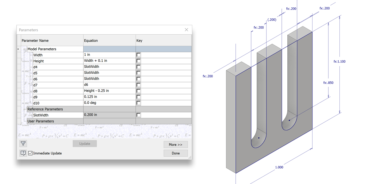
I also prefer to let the computer do the math whenever possible. For example, I have a rectangle and want the width to be 1 inch and the height to be equal to the width plus 10 millimeters. What’s that you say, you did know you can mix and match units? It’s pretty simple as well, to do this I will create my width dimension and while creating my height dimension simply select the width dimension and add (+10mm) to the end of it…Voiles!! The Height will always be the same as the width plus 10 millimeters.
 Using Reference Dimensions
I try to do as much as I can with constraints and dimensions and add construction geometry only if I can’t get what I needed from constrains and dimensions. Here is a nifty little trick I use from time to time that lets me do just that. In the example below I have something that resembles a fork shape and I want all three sections to be equal in width (two sides and the middle gap) even when changing the overall width of the sketch. You could use construction geometry to do this and that works, however, you can also use Driven Dimensions to do this and it will make a more robust sketch. In this example I dimension one the edges, select the dimension and right-click on it to turn it to a driven dimension. Now I place dimensions for the other two sections and select the reference dimension to make them equal to the reference dimension. Once all three of these dimensions place it will make them all equal and the lower width dimension will control their overall size while keeping them all equal widths.
 Written by:
Garin Gardiner
Sr. Product Manager

Garin Gardiner is a Sr. Product Manager for the Inventor product line at Autodesk. Garin joined Autodesk in 2005 and has worked in QA, Product Management and Business Development. Prior to joining Autodesk, he designed roller coasters and worked for an Autodesk Reseller. In his current role, he manages the Nesting Utility and modernization for Inventor.


Add comment
Connect with: Log in
There are no comments