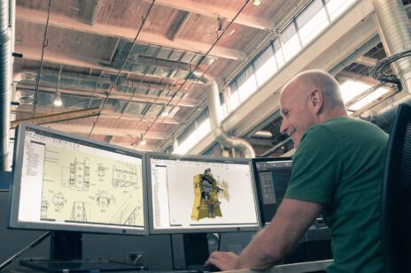
In part 10 of the Autodesk Inventor 101: The Basics series, we’ll take a look at how to setup a linear stress analysis using Inventor Simulation, as well as how to interpret results.
Any time that you are setting up an analysis, keep in mind the phrase “garbage in, garbage out.” This applies to all parts of the setup, from the location and type of boundary conditions, to accurate loading conditions, and even the proper selection of material for your parts. Fortunately for us, Inventor makes this process easy to understand in a left to right workflow across the ribbon. To see the details of setting up a simple linear stress analysis, take a look at the quick video below.
If you’re looking for more help with Autodesk Inventor, please make sure to check out the Autodesk Inventor YouTube channel. If you have more specific questions about Autodesk Inventor, please feel free to reach out to our experts on the Autodesk Inventor forums.


Add comment
Connect with: Log in
There are no comments