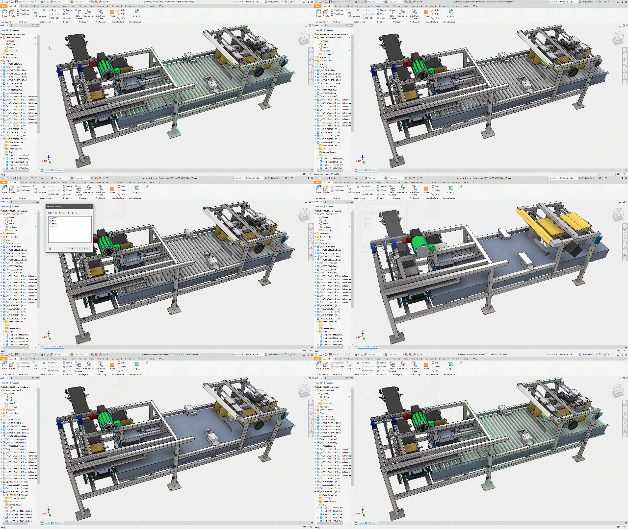
Have you ever wanted to show multiple versions or multiple options for your design?
Have you ever wanted to temporarily suppress components from your design model?
Have you ever wanted to show your design in multiple positions, locations, or configurations?
Have you ever wanted to create a simplified version of your design model for simulation, to reduce file size, or for export?
I’m sure that you have – and I’m sure you’ve been using iFeatures, iParts, iAssemblies, iLogic, substitute/shrinkwrap LOD’s (Level of details representations), derived parts and Positional representations to do it!
Autodesk Inventor 2022 gives us brand new functionality called ‘Model States’ that replaces some of these tools to make all of these existing workflows simpler and allow some new workflows which we couldn’t have before.
Click this link to find out what else is new in Inventor 2022.
Quick links:
- Model states
- Component families
- ‘Flexible’ components
- Manufacturing stages
- ‘Top Down’ simplification
- ‘Bottom up’ simplification
- Drawings of simplified models
- Configuration
- Design options
- BOM data
- Drawings and parts lists
- Vault support for model states
- iLogic and API support for model states
- What don’t Model states do!
- Migrating LOD’s to model states
- Conclusion
Autodesk Inventor 2022 Model states
You can now create multiple representations of a part or assembly within a single document.
This new workflow provides a convenient way to manage model variations for design, engineering, and manufacturing.
Because the design variations exist in one file, there is no need to worry about generating and managing member files on disk.
Each Model State can contain different:
- Features – Computed or Suppressed
- Components – Computed or Suppressed (Assemblies only)
- Constraints – Computed or Suppressed (Assemblies only)
- iProperty values
- Parameter values
- Bill of Materials (Assemblies only)
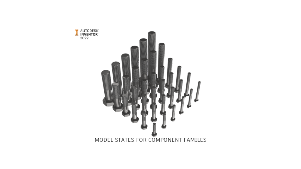
Model states for component families
Model states can be used to create component families – much like iParts.
The difference between an iPart and a Model state, is model state member variation is stored within the component file itself – there is no need to create and manage additional member files.
Each member can have its own suppression states (features or parts), parameter values and iProperties (Including part numbers) with the ability to edit designs globally (edit factory scope) or per individual member (edit member scope).
iParts are not going away, your existing iParts are supported in Inventor 2022. You’ll still be able to use iParts when you need to.
For example, you’ll still need to use iParts when creating content center components.
iParts might be the best option if you are managing your files in Vault basic, and you want to be able to track individual members (See more on Model states at Vault below).
Model states for ‘Flexible’ components
Sometimes, we have a part which is designed to be modified during assembly. For example, a sheet metal bracket which is angled to fit during assembly.
The Part number of this component will remain the same, but we may want to show it in our model in it’s assembled state, rather than how it looked when it came off the production line.
In our example, a Model state could be created on the fly to override the parameter that controls the angle of the bracket, representing our component at the assembled angle.
This would keep the same part number but would not generate additional member files on disc.
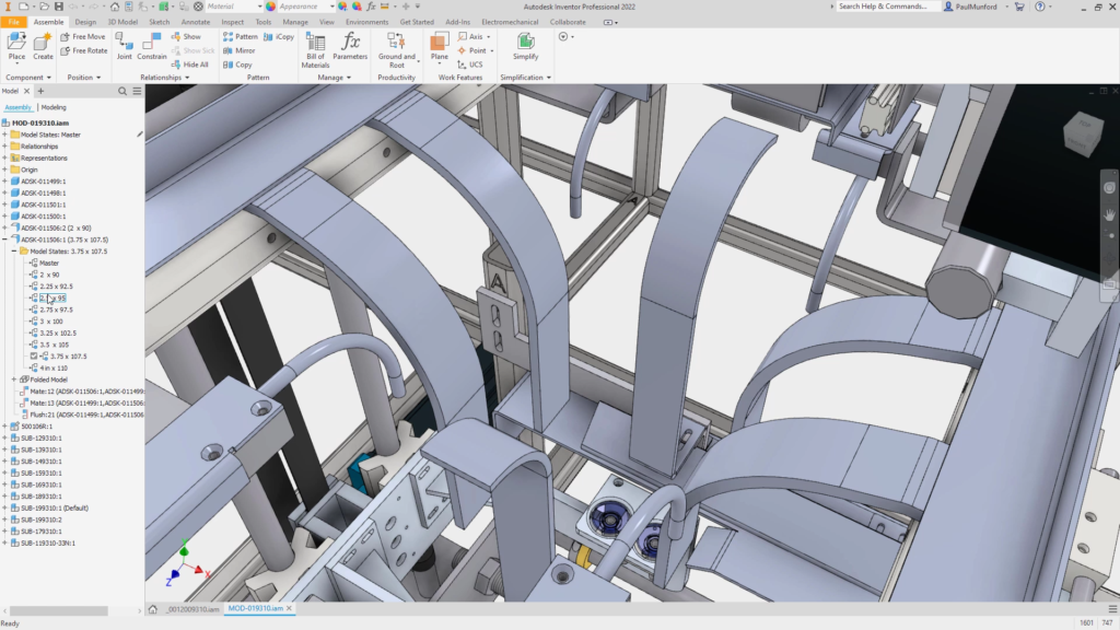
Use model states in Inventor 2022 to create components who’s shape changes during assembly.
Model states for manufacturing stages
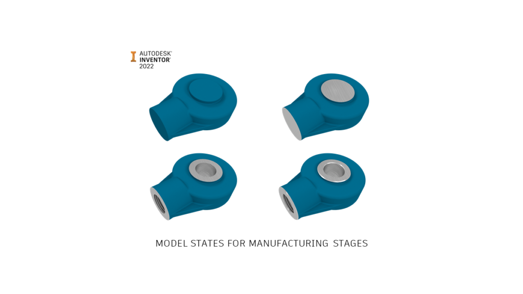
Model states provide a great workflow for visualising how a component might look at different stages of the manufacturing process.
For example: Cast > Machined > Drilled > Finished.
In the past, we may have used derived parts to show manufacturing stages. This may have involved creating a string of derived part files on disc – with the file management overhead that implies.
We can now show each model state of the component using model states, and we only have one file to manage on disk – with no derived relationships.
Sheet metal components could have model states with unique folded features and flat patterns representing each stage in the cutting and folding process.
Weldment assembly model states could contain unique weldment preparation, weld, and machining features.
Model states allow manufacturing stages to be easily copied and edited. For example, for CNC programming, you may require a version of your design with some features removed that aren’t required for tool paths.
It’s simple to copy a Model state, suppress the components that aren’t needed and begin programming!
Model states for ‘top down’ simplification
You may want to simplify your design before using the model for simulation.
You may want to simplify your design before sharing it with partners, to protect your IP.
We often want to simplify our model before sharing our design with Revit as part of a BIM project.
Model states can be used to replace an assembly model with a substitute – a derived part file containing simplified geometry, previously known as a ‘Shrinkwrap’, or Substitute Level of Detail (LOD).
A substitute model is great for reducing the load on your PC. For example, you may want to place multiple copies of your production machinery into a model of your factory layout.
Instead of loading a 10,000 component model into your top-level assembly 5 times (50k components in memory!), you can place your design using it’s substitute, meaning you only have to load 5 components into memory.
Because substitutes are derived, they retain their link to the master assembly. When you update the master assembly, the substitute will also update.
And Model states can do more.
Model states for ‘bottom up’ simplification
Model states in part files can be used to suppress features that aren’t required for your simplified model.
Model states in part files can also be used to add features (such as bounding boxes) that are only required in a simplified state.
Model states in part files can be linked to model states in assembly files using the Assembly Productivity Tool ‘Link Model states’ (Previously Link LOD’s).
This allows a change in model state at the assembly level to trigger a change in model state at the component level, propagating to all components that share the same Model state name.
This allows a brand new ‘Bottom up’ method of simplification that we haven’t seen before.
You could include simplified model requirements in your templates and CAD standards, knowing that they can be triggered when placed into the containing assembly.
Model states for drawing simplification
‘Bottom up’ model state simplification could be particularly useful when creating drawings from large assemblies.
The challenge with drawings created from large assemblies, is that Inventor is trying to calculate which edges of components will be seen in the drawing.
In fact, a drawing view created from a large model may have many overlapping edges, which Inventor will work hard to calculate, but which don’t add clarity to your drawing.
When simplifying using model states, each part is simplified – rather than the whole assembly being simplified as one lump (as with the substitute workflow).
Unlike creating a drawing view from a substitute model, when you create a drawing view which references a simplified model state, you’ll be able to take advantage of a faster loading drawing, and still be able to identify each component with an item number balloon, or pull data from individual components with a leader annotation.
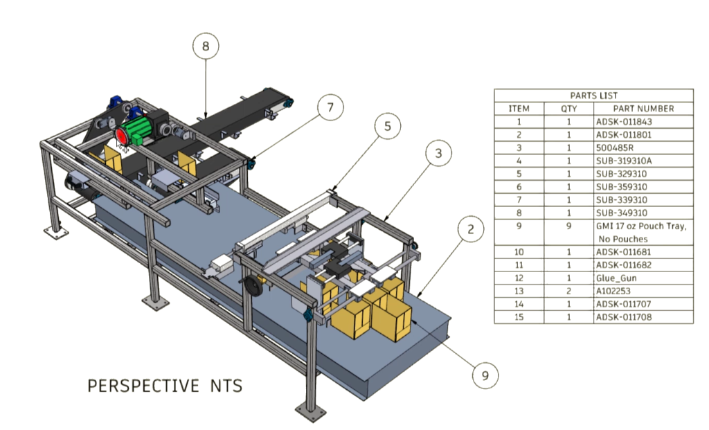
Use a simplified model state to create a simplified drawing view
Model states for Configuration
Model states for parts allow multiple design options within one part file – they can be used instead of iParts.
Model states for Assemblies control the suppression state and patterning of components, and can be linked to sub-component model states. In this way model states can be used instead of iAssemblies.
iAssemblies continue to be supported in Inventor 2022, and your iAssemblies from previous versions will migrated to Inventor 2022.
Unlike iAssemblies, all model state member information is contained within the component files, so there are fewer files to manage.
iLogic and the Inventor API’s fully support model states for parts and assemblies. Vault supports model states and the Vault Professional item master can be used to track individual files which contain multiple model states which have different Part numbers.
Model states for design options
The path to our final design is never smooth. Along the way there are many ideas and requirements to incorporate. Defining, managing, and coordinating all the variations of our design can be a headache.
Using Models states, it’s easy to create a new Model state for each new variation of the design. Each option can be defined, tested, and evaluated as the project progresses.
As design options are ruled out, the corresponding model state can be eliminated – leaving only the final design.
Because all the model state data is stored within the assembly or part files, no additional files are created on disk, and no file management clean-up is required.
Model states for BOM data
In assembly files, model states can control the quantities of component in the BOM using patterning and suppression.
This is reflected in the assembly BOM and parts lists. Components that are completely suppressed will appear as a line item in the BOM/Parts list, with a quantity of 0 (Zero).
Model states for drawings and parts lists
Model states can be referenced into drawing views for design documentation.
A parts list can be placed referencing a view of a Model state contained within an Assembly file. The parts list will reflect the BOM of the assembly model state.
Different views on the same sheet can reference different model states.
Because all the views are referencing the same file, overhead is reduced and updates to the design are simpler and quicker to execute.
Vault support for Model states
Components with model states can be stored in Vault in the usual way.
With Vault, you can:
- Check-in a model state file from the Inventor Vault add-in to the Vault client.
- Open and place a model state file from Vault.
- Assign items to model states with different part numbers.
- Map item properties to model state iProperties.
When opening or placing a component from Vault, you can choose which model state to display.
Only files necessary to open the specified model state to the local workspace are downloaded. Components suppressed by the model state are not downloaded.
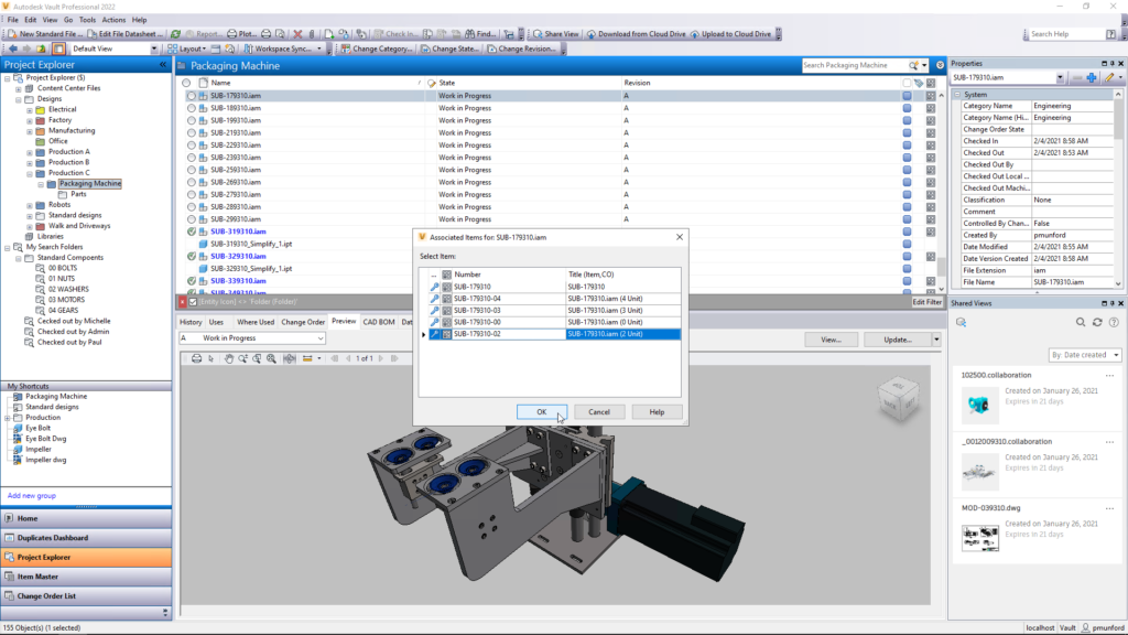
Autodesk Vault Professional 2022 supports Inventor model states, and can automatically map model states to Items
Each model state can have its own part number. Model state data is captured within the component file. Multiple components can be represented inside one file.
This could make components that are contained in the same file difficult to track with Windows file explorer or even Vault basic. In this case iParts may suit your workflow better.
With Vault professional, Items can easily be created for each Model state to help you track each member as if it was a separate component.
Click here to find out what’s new in Vault 2022
iLogic and API support for Model states
Model states are supported by iLogic and the Inventor API.
For more information, check out the revised snippets in the iLogic editor or click this link for the developer help.
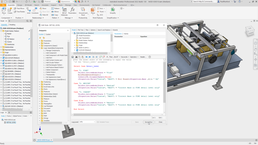
iLogic fully supports model states in Inventor 2022
What don’t Model states do!
The new Model states workflow in Inventor 2022 rolls a lot of existing functionality into one tool, with a few exceptions.
Model states remain separate from Representations – View Representations and Positional Representations (view-reps and pos-reps)
View representations control which components are visible, which components have colour overrides, and the camera view.
New in Inventor 2022 is the ability to reference the model’s camera view when creating a drawing view.
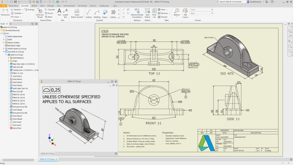
Model cameras can be used to create drawing views. 3D model annotations associated with a model view, can automatically populate a drawing view.
Positional Representations control overrides to constraints, including the suppression of constraints. This allows the same assembly to be shown in different positions, or even deliberately under-constrained.
Under-constrained sub-assemblies can be made ‘flexible’ meaning that they are free to move within their containing assembly and can be affected by the top-level assemblies constraints.
View and positional representation cannot be ‘linked’ from the top down with an automated tool like ‘Link model states’, but they can be linked manually.
Changing the top-level assembly’s view rep can trigger a change in a component view rep and changing the top-level assembly pos-rep can trigger a change in a sub-assemblies pos-rep.
The same design can have a model state, view-rep and pos-rep – each independent of the other.
Model state migration
Custom Levels of Detail (LOD’s) from previous releases are converted to Model States when you open them in Inventor 2022.
The BOM associated to a migrated LOD will display as it did before and not how a new Model State BOM will appear.
In a BOM migrated from a LOD a BOM row with a 0 (Zero) component state will not appear.
In a BOM with a model state active, with all components suppressed, the BOM row will appear and will have a quantity of 0 (Zero).
To upgrade an migrated LOD to a model state, create a new model state.
Autodesk inventor 2022 model states conclusion
Model states in Inventor 2022 represent the biggest change in the underlying structure of Inventor since it was first released.
Although it’s been a big change to the code base, Model States simplify functionality while allowing new workflows that weren’t available to us before.
Do you have questions on Model states in Inventor 2022? Please leave a comment below.
Would you like to offer your feedback on Model states in Inventor 2022?
Please click this link to add your suggestions to inventor ideas
