In this post, we’ll be looking at how to create a horn in MCG. The secret sauce to this tool requires two main ingredients:
- Transformation matrices
- The QuadMeshStrip operator.
To create a horn, the idea is to apply a sequence of transformation matrices to a collection of circular points to create the structure of the horn. Once all the points are in place, they can be meshed together with the QuadMeshStrip operator.

A Quick Matrix Rundown
If you’re new to matrices, Khanacademy has a great tutorial on the basics of matrix transformations, and codinglabs does an excellent job at explaining the use of matrices in 3D applications. For this post, we’ll confine our understanding of matrices to little machines which have two important properties:
- Property 1: A matrix can transform a vector into a new vector by scaling it, rotating it, and translating it. In the diagram below, the matrix M transforms the vectorVin into the new vector Vout.

- Property 2: Two matrices can be multiplied to create a new matrix. The new matrix does the same work as the two input matrices in the same order they’re specified. In the diagram below, matrix C is the result of multiplying matrix A by matrix B. When we use matrix C to transform a vector, the work of matrix A will occur first, followed by the work of matrix B.

If you’re following along with your own graph, be mindful that the input order for matrix multiplication matters. In mathematical terms, matrix multiplication is generally not commutative, meaning that the result of A*B is generally not the same as B*A.
Finally, for the technically inclined, here are a few more details relating to matrices and vectors in MCG:
- Matrices are 4×4 row-major, meaning that the translation component occupies the bottom row.
- Matrix rows are indexed starting at 1, so the translation component can be accessed with an index of 4 with the MatrixRow operator (or with the GetMatrixTranslation operator).
- Matrix multiplication is post-multiplicative (top-down), meaning that the “x” input of the Multiply operator will occur before the “y” input.
- When a vector is transformed by a matrix, the vector is assumed to be a point (with a “w” component set to 1), and is therefore affected by the translation component of the matrix.
Stacking Cubes with Matrices
Now that we’ve got a sense of what matrices do, let’s look at how to use them in MCG. Open the MCG editor, replicate the graph below, and save it as cube_stack.maxtool. Note that it shouldn’t compile yet – we still have to define the array of matrices to feed into it.

Now, to create this array of matrices, we’ll use the GenerateN operator. This operator incrementally builds an array of values by running its “next” function repeatedly. The “next” function receives only one input: either the previously computed result, or, on the first iteration, the “first” value connected to the GenerateN operator.

Here, on the first iteration, the function’s input is set to the MatrixIdentity (I) and is multiplied by the translation matrix (Z). You can imagine the MatrixIdentity as a matrix which performs no work, much like multiplying a number by 1. We’ll label the result of this first iteration as matrix R1.

On the second iteration, the function’s input is set to the previous result: matrix R1. R1 is then multiplied by the translation matrix Z, resulting in matrix R2.

When we expand this sequence of operations, we can see that R2 = R1*Z = (I*Z)*Z = Z*Z. In other words, R2 amounts to multiplying the matrix Z with itself twice. By extension, on the nth iteration, matrix Rn will be equivalent to multiplying the matrix Zwith itself n times.
With the array of matrices properly generated and applied to each cube, you can now evaluate the graph and create an instance of the cube_stack in your scene (Create > Max Creation Graph > cube_stack).

Twist and Bend
Let’s spice things up with some twists and bends. In the graph below, be mindful to add the correct RotationXMatrix, RotationYMatrix, and RotationZMatrix operators (instead of copying and pasting the same RotationXMatrix operator three times). Make sure to also convert your Parameter values into radians using the ToRadians operator.

When you evaluate the graph, you can now manipulate the local rotations in X, Y, and Z. Notice that larger rotation values will cause tighter curls.

Scaling
The last piece of this matrix puzzle is to add a scaling factor along the stack. Use the ScaleMatrix operator to affect the scale uniformly along the X, Y and Z axes. Alternatively, if you’re looking for more control over the scale along each axis, consider using the VectorScaleMatrix operator instead.

When you evaluate your graph, the scale parameter should now affect the scale along the stack.

A Circular Base
With the horn starting to take shape, let’s switch gears to focus on the circular base. Open a new tab in the MCG editor (File > New), build the following graph, and save it as horn.maxtool (it shouldn’t compile yet). Once again, we’re starting off with a mapped function to clone some cubes, but this time, we’ve chosen to use the OffsetMesh operator to move each cube by a given vector.

To create the circular array of points, we’ll use the RangeExclusiveFloat operator, which produces an array of evenly spaced values between 0.0 and 1.0 exclusively. For example, given an input of 5, it will produce the array containing the following five elements: [0.0, 0.2, 0.4, 0.6, 0.8]. This operator is ideal for generating proportional values, and we’ll be using it to create evenly distributed points around a circle.

In the graph above, the TwoPi operator denotes the angle (in radians) contained inside a full circle. We’re multiplying it by the current proportion to obtain the current angle in the circle. This angle is then applied to the Cos and Sin operators, whose results are multiplied by the radius to obtain the (X,Y) cartesian coordinates of the point on the circle.
Evaluate the graph, and create an instance of the horn in your scene (Create > MaxCreationGraph > horn). If everything went well, you’ll see a circular distribution of proxy cubes around the local origin.

Making Rings
At this point, we’ve got a circular base and a sequence of matrices which defines the horn’s shape. The next step is to glue these two pieces together to create rings along the horn. Open a new tab and build the graph below. Save this graph asTransformPoints.maxcompound under your C:\Users\<username>\Autodesk\3ds Max 2016\Max Creation Graph\Compounds\ folder. Once this compound has been saved, select Operators > Reload Operators, and close the tab. We’ll be using this compound shortly.

Next, go back to the cube_stack.maxtool tab, and copy (Ctrl+C) the section which generates the array of matrices.

Paste (Ctrl+V) this section into the horn.maxtool tab, and use two Pass-through: Array nodes to bring the array of matrices and the point profile closer together. You can also take this moment to align the proxy cube section to keep your lines clean.

Add the following operators between the Pass-throughs and the proxy cube section. You’ll notice that we’re using the TransformPoints compound we created above to transform the point profile according to each matrix. Apply the Flatten operator to obtain a flat array of vectors instead of an array of sub-arrays of vectors. You can then feed this array into the proxy cube creation, and change the size of the proxy cubes to 0.5 to get a clearer result in the viewport.

When you evaluate the graph, your point profile should now appear as a sequence of rings. Note that the cubes themselves are not oriented along the ring, since we’re only affecting their position with the OffsetMesh operator. This is fine, because we’ll be replacing these cubes with a continuous mesh in a moment.

Meshing it All Together
The final step involves meshing all the points together. Remove the proxy cube section (along with the Flatten operator), and add the following operators. The QuadMeshStrip operator produces a QuadMesh output type, so we’ll need to use the ToTriMesh operator to make it compatible with the terminal “Output: geometry” node’s TriMesh input type.

At its core, the QuadMeshStrip operator takes a flattened array of vectors, and connects them together row-by-row using quad faces. Here’s a breakdown of its inputs:
- points – The array of vectors. In this case, we need to reverse the incoming array of sub-arrays before flattening it to make sure the mesh’s faces are built with the correct normals. If your mesh appears with incorrect normals in your renders, it’s likely you’re missing a Reverse operator. In fact, I strongly recommend you create test renders of your MCG tools as you work on them.
- nRows – An integer which denotes how many rows are contained within in the flattened array of vectors. It’s assumed that each row contains the same number of points.
- bWrapRows – A boolean which determines whether or not to connect the first and last row of points together. We’re setting it to False because we don’t want the horn to loop onto itself.
- bWrapCols – A boolean which determines whether or not to connect the first and last point on each ring. We’re setting it to True to make sure our horn appears as a fully extruded cylinder (instead of having a missing column of faces along its length).
When you evaluate the graph, your horn should now appear as a continuous mesh in the viewport. As a final touch, add a CapHoles and a Smooth modifier (with AutoSmooth enabled), and tune your horn as you see fit. You can also use a Symmetry modifier to add the second horn.

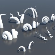
With that, your horn tool should be complete! Make sure you experiment with different designs, and add your own customizations to the tool! Here are a few horns we discovered with this technique:

Download: horn.zip
Instructions: Extract the file anywhere on your filesystem, then go to Scripting > Install Max Creation Graph (.mcg) Package, and select horn.mcg in the extracted location. Once the package is successfully installed, it should appear under the Create tab > Max Creation Graph > horn.


(0)