In the previous post, we covered the basics of “reading” an MCG function to identify its inputs, its output, and the operators which compose its “body”. In this part, we’ll cover some useful techniques to help you build your own MCG graphs and functions. To see these techniques in action, we’ll be walking through the creation of the following staircase using a combination of MCG and some simple Box primitives.

Whether you’re writing a whole graph or a single function, it can be quite useful to sketch out an image of what you’d like your final result to look like. While you do this, note down any variables or “control knobs” you would like to have at your disposal to drive your final result.

For this staircase, we’ll want the total number of stairs to be driven by the “num stairs” variable. The dimensions of a single stair will be driven by the “width”, “depth”, and “height” variables. Likewise, the spacing between each step will be driven “Y-spacing” and “Z-spacing” variables. There’s no need for an “X-spacing” variable here, since our staircase needs to maintain a fixed value of 0 in X to “grow” in a straight line along the Y-Z plane.
Now that we have a good idea of the variables we’ll need, we’re ready to jump into MCG. Start by creating an Output: geometry node. In the screenshot below, we’ve connected an EmptyMesh to the output node to let us properly evaluate the graph and to show the Staircase tool under Create > Geometry > Max Creation Graph.

The next step is to create a parameter node for each variable in our sketch. The “num stairs” variable is best defined by a Parameter: Int32 node, since we want to constrain the value to integers instead of decimal numbers. By contrast, our other variables should be defined as Parameter: Single nodes, since we want to treat them as decimal values.

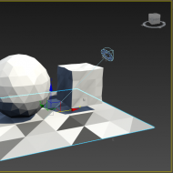
With the parameters in place, connect the “width”, “height”, and “depth” into a CreateBox operator to create a TriMesh, and connect the CreateBox’s output to the graph’s terminal node.

Test your graph by selecting File > Save (CTRL+S) and then Build > Evaluate (CTRL+E) in the MCG Editor. To create a Staircase object, go to Create > Geometry > Max Creation Graph > Staircase, then click on where you want to place your staircase on the grid.

The result might seem a bit underwhelming – a single stair is a far stretch from a staircase – however you’ll notice that the stair TriMesh we’ve produced reacts correctly to the changes in its width, height and depth, so we’re on the right track!
To create multiple stairs, start by connecting the “num stairs” parameter to a Range operator, and connect the Range to a Map:

The Range operator produces an array of integers from 0 to n exclusively, meaning that an input of 5 will produce the array: [0, 1, 2, 3, 4]. More generally, given an input “n” representing our number of stairs, the Range operator will produce the array: [0, 1, 2, …, n-1 ].

So how does an array of integers help us create a whole staircase?

Recall that we can use the Map operator (i.e. the “wizard” from Part 1) to apply a function (or a “formula”) to each item in an array to produce an array of transformed items. The challenge here is to build the right formula. Let’s head back to our sketchbook to see how to build it:

The integer array on the left represents the Map’s input array, which is generated by the Range operator. The value “i” here symbolizes an arbitrary value in the array. To keep things simple, let’s position stair number 0 at [0, 0, 0].
According to the “Y-spacing” and “Z-spacing” variables (represented here by Δy=3 and Δz=2), it follows that stair number 1 should be positioned at [0, 3, 2], and that stair number 2 should be positioned at [0, 6, 4], and so on:

Based on this pattern, we can compute the position “pi” of stair number “i” as the scalar multiplication of the vector [0, Δy, Δz] by i. In other words, our formula to obtain the position from a given integer is: pi = i x [0, Δy, Δz]. Therefore, the position of the last stair can be computed as: pn-1 = (n-1) x [0, Δy, Δz].

Now that we know how to compute the position of each stair, we can use the OffsetMesh operator to move each stair to its correct position. If you’re more comfortable with reading pseudocode, here’s what the chain of function calls might look like:
CreateStair(int i):
  return OffsetMesh(CreateBox(width, height, depth), i*[0, Δy, Δz]);
So how do we write this function in MCG? Start with a Pass-through node whose type matches the type contained in the input array. In this case, we’ll start with a Pass-through: Int32 because the Range operator creates an array of Int32’s.

As we continue building our function, we’ll keep this Pass-through’s input unconnected, to make it act as the function’s input. To label it, first select it, then right-click and choose “Create Group Node”. Double-click on the group’s title bar, and type “input: i”. This labeling technique can help you quickly identify where your function’s arguments are coming from.
It’s worth noting that this Pass-through node is actually entirely optional, and only serves to increase the “human-readability” of the graph. Remember that at the end of the day, the MCG compiler isn’t concerned with a function’s aesthetics; it will only look for the unconnected inputs contained within a function’s body to determine the function’s inputs.
The next step is to create the spacing offset between each stair. Connect a constant of 0.0 to a Vector3’s X input, and connect the Y-spacing and Z-spacing parameters to its Y and Z inputs.

To multiply this spacing offset by the input integer, place a MultiplyByScalar operator and connect its “v (Vector3)” input to the Vector3 node.

You’ll notice that the “amount (Single)” input only accepts a Single value, so use an IntAsFloat operator to convert the input integer into a Single value. The terms “Float” and “Single” are interchangeable in MCG, and both refer to “Single-Precision Floating Point” numbers (i.e. decimal numbers).
To place each stair at its appropriate position, connect the MultiplyByScalar and the CreateBox operators into an OffsetMesh. Complete the function by connecting the OffsetMesh’s “function (Func)” output to the Map’s function input. This way, the result of OffsetMesh will be returned by the function.

To summarize the graph so far, the Map operator accepts the Range’s array of integers, and produces an array of TriMeshes. The last step is to connect a CombineAllMeshes operator to convert the array of TriMeshes into a single TriMesh.

You can now press Save (CTRL+S) and Evaluate (CTRL+E) to update the Staircase geometry tool. If you used the same default values as the ones in this tutorial, you should obtain the following Staircase object in your scene:

When you’re satisfied with your staircase’s layout, hold Shift and move the Staircase along the X axis to copy it. Change the width, depth and height of the new Staircase, and move it up in Z to create the following sequence of rail posts:

Hold shift and drag the rail posts along the X axis to copy it to the left side of the stairs:

Next, create two box primitives and align them to the top of your rail posts to complete the handrails.

Because the rail posts and handrails of the staircase exist as separate objects, they do not react to changes made to the original Staircase’s parameters. To implement this synchronization, you can attempt to wire the “num stairs”, “X-Spacing” and “Y-Spacing” parameters of the rail posts to the main staircase, however this approach will also require more work to align the handrails properly (possibly via scripted controllers):

A more robust alternative is to generate the whole staircase in MCG, including the rail posts and the handrails. There are many ways to achieve this, and if you’re looking for inspiration (or if you’re feeling adventurous), feel free to install and explore the StairsAndRails.mcg tool linked below.

The StairsAndRails object lets you assign a Multi/Sub-object material to adjust different parts of the geometry:
- Material ID 1: stairs
- Material ID 2: rail posts
- Material ID 3: hand rails.

Within the StairsAndRails graph, the Material ID assignment is highlighted by the red groups, and is performed using a more advanced MCG technique: “function application”. This technique lets you apply the same function in different parts of your graph, to avoid re-using the same operators repeatedly.

We’ll be exploring function application and other techniques in later posts, so stay tuned!
Download: StairsAndRails.zip
Instructions: Extract the file anywhere on your filesystem, then go to Scripting > Install Max Creation Graph (.mcg) Package, and select StairsAndRails.mcg in the extracted location. Once the package is successfully installed, go to Create > Max Creation Graph > StairsAndRails, and click on the grid.


(0)