In this post, we’ll be venturing into the creative land of “Low Poly” art. This art style features the use of contrasting faces and sharp edges to highlight the scene’s simple geometry. This form lends itself to the creation of “tiny island worlds”, and is an ideal stepping stone for 3D newcomers.

You can achieve this look in a variety of ways, and I strongly encourage you to tinker and discover the techniques that work for you. When I first dabbled in this style, I found that applying a “smooth” modifier (with no additional settings) was an easy way to reveal an object’s triangular faces.

This step alone worked well for curved surfaces, but it didn’t produce the same effect on the planar surfaces of boxes and planes. Adding a “noise” modifier helped to randomly perturb the object’s vertices, and by extension, the orientation of each face. This way, each face would become more perceptible based on the scene’s lighting conditions. The compromise, however, was that the geometry could no longer contain planar faces, and would usually appear slightly “crumpled”.

This simple workflow is great for creating rolling landscapes with rocks and gnarly trees, but what if you really wanted to keep your surfaces planar? What if you wanted to color the triangles in different shades of blue without having to tune your scene’s lights?
My attempt to answer these questions resulted in the “Low Poly” MCG modifier, which you can download at the bottom of this post. If you’re interested in the finer details of how it was built, feel free to fast-forward to Part 2. In the remainder of this post, we’ll be covering how to use this modifier to render a “Low Poly” scene.
Once you’ve downloaded and installed the LowPolyMod.mcg, you can apply it as a modifier to an object. This modifier removes the object’s smoothing groups, and applies random noise to each vertex. It also uses the vertex color map channel to color each face based on its orientation along the Z axis. This way, faces pointing upward will appear brighter, while faces pointing downward will appear darker.
To see this change in brightness, select the object, then right-click and go to “Object Properties”. In the “Object Properties” window, enable “Vertex Channel Display” and press the “Shaded” button. If you forgot to press the “Shaded” button, your objects may appear entirely black in the viewport.

In the rollout, enable “Keep Vertices” to cancel out the vertex noise. Try increasing the noise in X, Y, and Z to affect the brightness of each face. You can also change the seed parameter to explore different noise permutations.

To color your objects, open the material editor, and create the material graph below. The idea is to use a “Mix” map to interpolate between two colors, defined here by two “Color Correction” maps. These two colors are mixed according to the mesh’s vertex color map channel. In this case, darker faces will appear greener (Mix Color 1), while brighter faces will appear more blue (Mix Color 2).

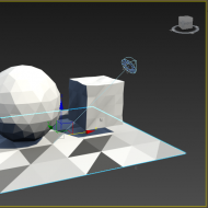
When you assign this material to your objects, you might notice an inconsistency in how the material is displayed in the viewport. Despite this inconsistency, the material should behave correctly when it’s rendered. In the comparison below, the dark faces in the viewport are correctly rendered as green faces, while light faces are rendered as blue faces.

Now that we have an idea of how this modifier works, in the next part, we’ll be taking a deeper dive into how it was built. See you in The Low Poly Modifier Part 2!
Download: LowPolyMod.zip
Instructions: Extract the file anywhere on your filesystem, then go to Scripting > Install Max Creation Graph (.mcg) Package, and select LowPolyMod.mcg in the extracted location. Once the package is successfully installed, it should appear in the modifier drop-down list.


(0)