Have you ever wondered what those frequency studies are used for? Let’s take a look at an example using the reciprocating saw seen above. Anytime there are moving components such as motors, there is going to be some level of vibration in the model. The question is whether that vibration is going to cause discomfort to the consumer or even worse, a product failure!
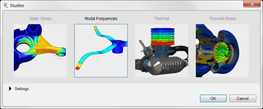
Fusion 360 offers a great interface for running several types of studies (Linear Static, Frequency, Thermal Heat Transfer, and Thermal Expansion). Let’s get started!
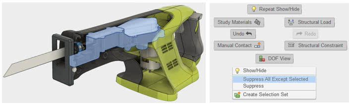
When working with FEA simulations on assemblies it’s important to reduce the components we’re analyzing to the ones we are focusing on.
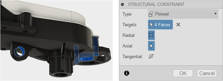
Next we will describe how the parts are held down using constraints. This is where we need to be careful not to over constrain the design or make it too rigid. The pin constraint enables us to constrain cylindrical faces in the radial, axial, and/or tangential directions depending on the behavior.
At this point we have constrained the gear housing. What about the other components? Are they free to move? We can check this by clicking on the DOF command (Degrees of Freedom). This command will show in color the components that are free, fixed, or potentially fixed. The gear housing is “potentially fixed” due to using pin constraints only.

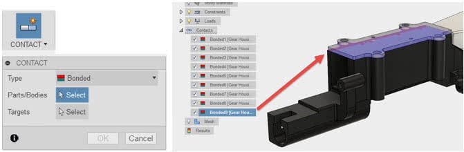
We can see the two covers are free to move. Let’s create bonded contacts between the components to ensure there is no free body motion that occurs on those components during the solve. Fusion 360 will automatically apply these bonded contacts to faces that are coincident to each other.
Now it’s time to create a mesh of the assembly. Or in other words we are going to break the models up into small pieces to be analyzed.
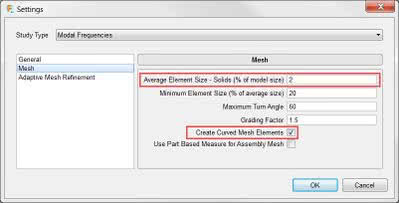
First let’s take a look at the mesh settings. We are going to change the average element size to 2% of the model size. And check the box to use curved mesh elements. This setting will add a mid-side node to the element allowing it to better represent the curved geometry on the model.
-

- Curved Mesh Elements Unchecked – Runs Faster
-
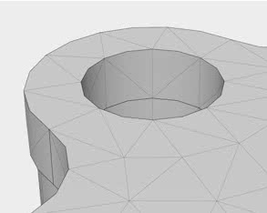
- Curved Mesh Elements Checked – Slower / Higher Accuracy
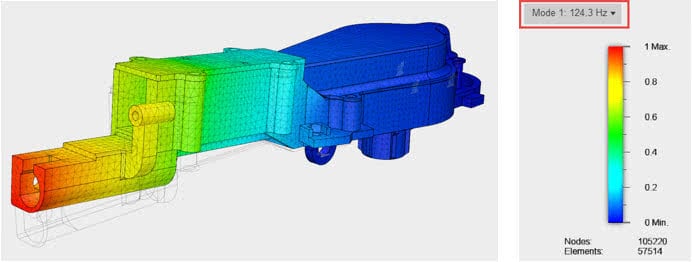
Next it’s time to run the solver which takes less than a minute. Taking a look at the results we can see that the blade end of the gear housing will vibrate 124 Hz if the model is excited. Our goal for this model may be to reach 1000 Hz for the first resonant frequency which is high enough to maintain customer satisfaction for comfort as well as increase the life of the internal components.
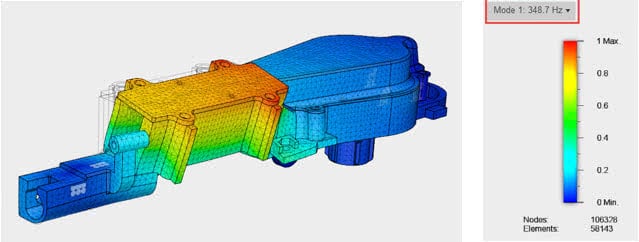
We can prevent this by adding tabs to the outer housing of the reciprocating saw and use them to suppress the vibration. We can simulate this before we spend any time creating the new 3D features in the design. Let’s add a couple frictionless constraints to the faces where the tabs will come in contact. The frictionless constraint only allows movement parallel to the selected face.

Now let’s run the solver again. We have increased the frequency value for the model. However the center of the gear housing has a tendency to twist at 348 Hz.
We will make one more modification to the design. Let’s add extrudes to the cylindrical screw bosses which will be attached to the outer housing of the saw.
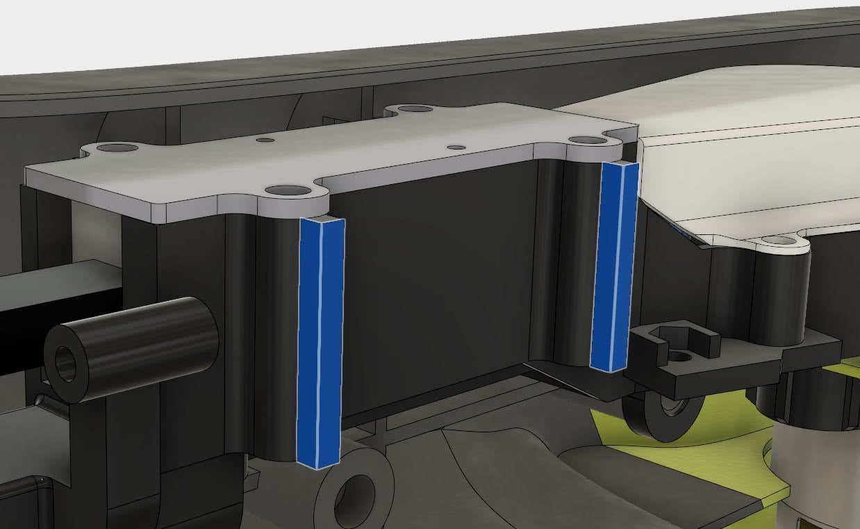
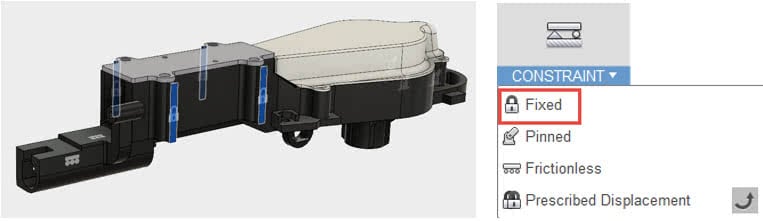
Then we will use fixed constraints on all four extrudes.
And finally run the solver. It looks like we have nearly reached our goal of 1000 Hz! At this point it would be up to the designer whether or not it is important to add more mass or stiffness to decrease vibration on the gear housing. As we make these changes it’s also necessary to take into account the cost of making additional modifications for manufacturing.
 Autodesk Fusion 360 is more than a 3D modeling tool. Use the simulation capabilities to solve for linear static, frequency, as well as thermal heat transfer and thermal expansion. Stay tuned for additional workflow blogs on other study types.

(0)