Validating your design commonly involves setting up and running an analysis that takes you beyond a simple linear static problem. Linear static studies are fully defined with material, a constraint, and a load. Anything beyond that and it gets a little scary. It’s like that first time you cross the wake on water skis. It looks impossible at first, but then you soon realize the water is fine on the other side. And it expands the possibilities for testing future designs.
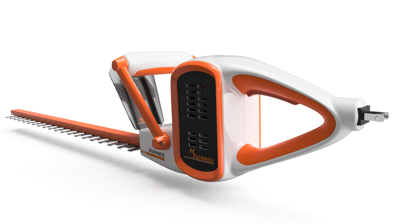
Let’s take a look at a snap fit study as an example. This hedge trimmer has a piece of trim that is snapped into place on both sides of the body. The goal is to test the stresses and deflection on the trim as it is installed. We also want to know how much force it takes to push the tabs through the slots.
The setup for this study is simple, but there are common mistakes that are made. We will be using the Event Simulation study type that comes with Fusion 360 Ultimate. Event Simulation is a powerful analysis tool that is intended to help you solve problems with complex contact, motion, large deformation and nonlinear material.
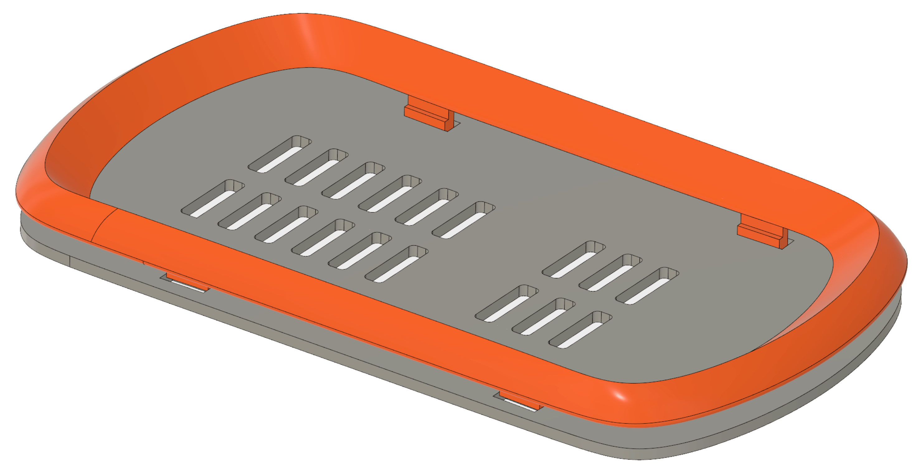
The first step is to simplify the model. We only need the trim and a portion of the housing. It’s not necessary to analyze all the mesh elements that won’t come in contact with the trim. It’s also a good idea to move the trim into position before contacting the body.
Then choose Event Simulation as the new study type. Seriously, look at all the fun we could have in this dialog.

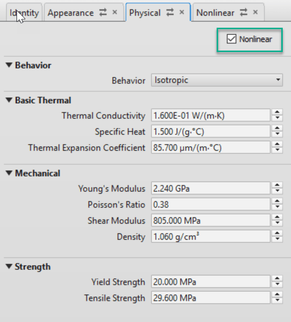
First, we’re going to choose the material for both of the components. All the physical properties are taken care of unless you would like to include a nonlinear stress-strain curve. Check the “Nonlinear” box in the physical properties tab and apply the data. There is also an option to select the hardening rule when including the Bauschinger effect in your results.

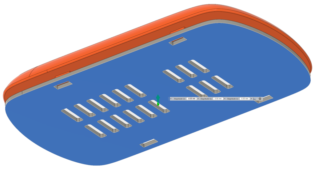
For the boundary conditions, let’s start with the load. In this study, we want to determine the force needed to snap the trim in place. Our load in the setup will be a prescribed displacement. We’re going to apply the displacement to the housing instead of the trim because the trim stretches a little. If we prescribe the displacement to the trim, it will apply a value in all three directions. In this case, it will force the Y and Z directions to be 0mm, and won’t allow the trim to bend. Also, note the curve multiplier for controlling load/displacement over time.

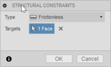
There are a few methods that come to mind for constraining the trim. First, we could select a flat face such as the one in the following image and apply a frictionless type to it. That prevents motion perpendicular to the face but allows parallel displacement.

Another option is to choose desired faces on the trim and apply a fixed constraint. We don’t want to fix all directions, so Y and Z need to be deselected.

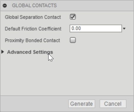
Be sure to specify the contact condition between components. In this case, we have Global Separation Contact checked. The system will automatically find the contact between the two components.
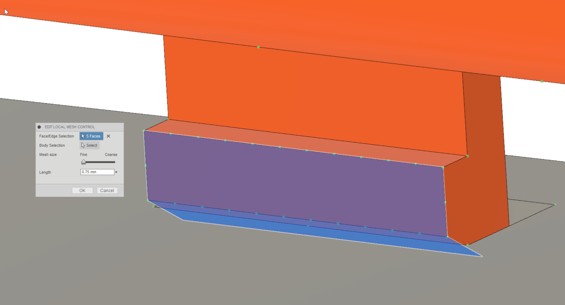
When you have contact conditions between components, it’s a good idea to refine the mesh in those areas. Here we are adding more elements to the two faces on the tab that are coming in contact with the housing. We even get a nice graphical preview of the element size before creating the mesh.
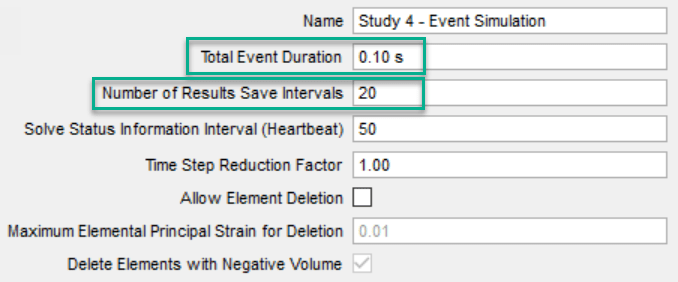
Before running the study we need to specify the Event Duration and Number of Results Save Intervals. Static studies assume the load is applied very slowly. Using Event Simulation we can apply the load at any speed. Be sure the Event Duration matches the Multiplier Curve in the load we applied earlier. There is even the option to allow element deletion in case the model geometry breaks during the simulation.
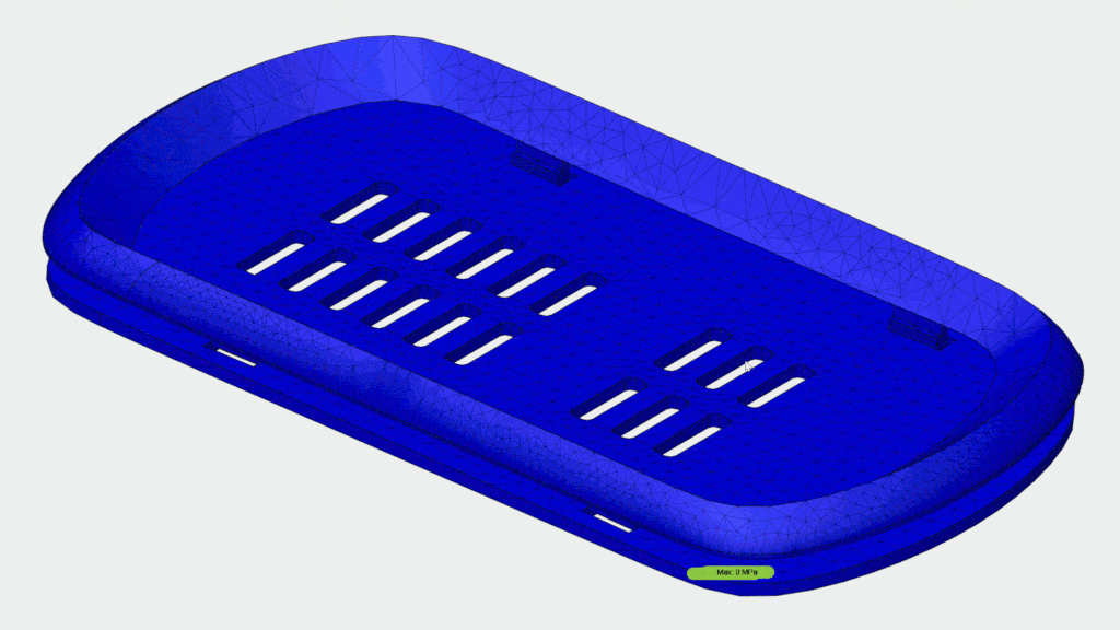
After running the study, we get results for all 20 times steps that can be played as an animation. We can see the stress and displacement of the model throughout the load duration. Also, observe the force needed to push the trim into place by checking the reaction force.

One other thought before I wrap this up. If the model is symmetric, consider running the analysis on a quarter of the geometry. It will run much faster which will free up time to run more studies on future design ideas. It will also potentially be more stable due to the frictionless constraints on the 3 faces in the following image. The two sectioned faces of the trim act as symmetry constraints.

I hope this article has helped to boost your confidence in spreading your wings as you test your designs. Again, don’t be afraid to test the water as you break down barriers and explore outside the wake of linear static studies.

(0)