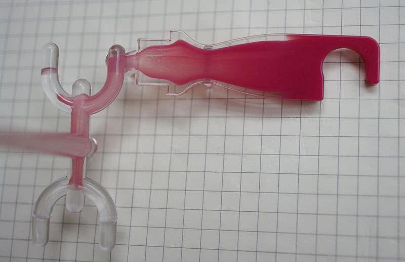
Sink
You may already know what sink marks are, but for those newer to the injection molding industry, they are depressions or cratering that occurs on the surface of parts. Think of sinkholes on roadways – the final effect is the same but the root cause is quite different. When a sinkhole occurs on a road or even just in a field, it is due to erosion under the surface. In injection molded parts, sinking and cratering occurs when there is uneven shrinkage in a part’s structure.
Sinking is most commonly caused by uneven wall thicknesses, improper cooling, insufficient mold pressure or improper gate placement. You are more likely to run into this issue if you are using acetal or polypropylene as compared to fiberglass based plastics.
To prevent this unwanted deformation, you can make changes in your part design as well as your molding process. In part design, we recommend maintaining as close to a uniform wall thickness as possible throughout the part. Also pay attention to where you place your gate or gates to make sure plastic is always flowing from thick to thin (as much as possible). In molding operation, a greater holding pressure and hold time will help prevent sink marks where possible.
Flash
Flash is described as the minor imperfections that occur around the edges of an injection molded product that result in a tiny lip of plastic caused by overflowing of the plastic in the molding channel. For many parts and manufacturers, flash won’t be considered a big problem. However, if you are working with tight tolerances or in need of fine aesthetics on the finished product, you may consider flash to be a major problem.
Flash is generally caused in the injection molding process, apart from the mold design. Resulting from insufficient mold pressure or low tolerances in the mold itself, it’s generally easy to fix.
You can increase mold pressure or add air vents to the mold to allow for faster cooling. However, if reworking the molds is going to be too big of a cost eater and your flash problem isn’t significant, trimming the excess off in post-production is generally enough to ensure a quality product.
Flow Lines
Flow lines are beautiful in simulation but in injection molding, they’re not quite desirable. These marks are often wavy lines that occur down the length of a part on surfaces due to improper cooling and faulty gate placement. Essentially, the injected plastic becomes partially solid before the forming process is complete, thus causing these minor, and sometimes major, aesthetic defects.
In the design process, you can try to prevent flow lines by maximizing your gate placement. In the actual injection molding process, adjusting the nozzle diameter, injection speed, mold pressure and cylinder temperature can help negate the effects of flow lines. Much like flash, the importance you place on eliminating flow lines in the molding process will be wholly dependent on your end goals for the finished product.
Short Shots
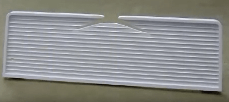
A short shot is exactly what you think it is – the injected plastic falling short of the other side of the mold. Ultimately this causes an incomplete component and is one of the more major defects in the injection molding process. If there are flow restrictions or delays during the injection process, short shots and incomplete molding can become a common problem. Another thing to consider is how the air in the mold is being vented out. If the air in front of the injected plastic is not being vented fast enough, it can cause a buildup of pressure and keep the plastic from injecting further.
For this particular major defect, you have to get to the root cause before you can begin to address the problem. If you believe it to be a result of a slow injection process or hesitation in the flow rates, try raising the injection pressure or the molding temperature. If there is a blockage or restriction in a molding channel, you will need to clear it before moving forward. And lastly, if you believe the cause to be a buildup of pressure, add venting channels to the mold to allow for proper air movement.
Burn Marks
As with any manufacturing process that involves heat, burn marks occur when the plastic is heated to a temperature beyond what it can normally withstand. Burn marks are usually aesthetic and don’t cause any problems in the actual functionality of the part.
Due to the fact that the plastic is physically burning, you can probably begin to guess how you can overcome or prevent this problem. Decreasing the injection speed or melt temperature should be the first things you try, but overheating could also be occurring due to trapped air. For the trapped air problem, adding vents should put you in the clear. Generally, dealing with burn marks is going to be more of a corrective action in the molding process than it is preventative. One could try to predict the defect, but largely it won’t be known until molds are actually being used.
Sources: InTouch, Rodon Group, AIM Processing, KandbMoldedproducts

![[2]](https://commons.wikimedia.org/wiki/File:Co-injection_(sandwich)_molded_part.jpg)
![[3]](https://commons.wikimedia.org/wiki/File:Plastic_Injection_Moulding_-Short_Shots_Defects.png)
(0)