When looking for a new car, one of the first things that draw in a buyer is the way the vehicle looks. If the car’s side panels aren’t aligned, if the front hood has a wavy appearance, or if there are depressions on the bumper, those can all have a negative effect on the potential buyer’s interest, portraying a low-quality product and the possibility of losing that sale.
This is one reason why upfront engineering is extremely helpful for many manufacturers within the automotive industry. With so many of the visible components of a vehicle now being created with plastic through injection molding, identifying shrinkage (side panel alignment), warpage (the wavy hood), sink marks (the depressions on the bumper) using Moldflow is handy to help manufacturers achieve that high-quality look they desire.
Part Shrinkage Prediction:
Analysis requirement:
Fill+Pack+Warp
What to look for within the simulation:
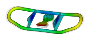
Shrinkage is a key influencer to how a molded part deflects, so the process for investigating and minimizing unnecessary shrinkage includes many similar approaches as addressing part warpage. Within Moldflow simulations, the warpage analysis includes analyzing the shrinkage, but enabling the feature, “Isolate Cause of Warpage”, prior to running the analysis will provide more detailed result plots including a set of results called, “Deflection, Differences in Shrinkage”. These plots display the amount of part deflection due to shrinkage variations. In addition to this plot, other Moldflow results including volumetric shrinkage, shrinkage compensation values, and even the fill result. How the material flows through the cavity (orientation of flow) can help identify where more shrinkage may occur.
How to approach minimizing material shrinkage:
Catching excess or unexpected shrinkage through simulation helps when designing molds, as traditionally, mold designers apply rule-of-thumb values for shrinkage based on the general material properties. Moldflow simulation can be used to either make additional steel-safe recommendations to tool designers, or, provide insights for reducing shrinkage if areas aren’t within tolerance. Some options for this may be to:
-
- Modify process settings: Experimenting with ranges of process settings, such as hold time/pressure or melt/mold temperatures, should be analyzed first to see if there is a way to process it out rather than more extensive changes such as mold changes. Note, however, that some process modifications may result in other concerns, such as an increase in internal stresses – for example, freezing the material with a colder mold to stop shrinkage.
- Explore gating options: If the shrinkage is directly related to flow direction, relocating the gate (or adding additional gates) may reduce areas with excess shrinkage. Running Flow simulations can help identify if this is an option, given the part geometry and gating restrictions.
- Identify high-shear regions: While reviewing Moldflow shear results, they often coincide with high-shrink areas due to the increased orientation as a result of shearing then the relaxation of polymer chains. Adding rounds/fillets, flow directors, or other part features to minimize shearing in the high-shrink regions may be helpful.
- Modify part geometry for uniform thickness: Variations in part wall thickness can result in different shrinkage rates. Adjusting the wall thickness of these regions can be simulated to identify if that is necessary, or if there are processing changes (ie. increase hold time/pressure, adjust mold or melt temperatures). The Moldflow parametric analysis generates a range of specified thicknesses to analyze the best option while comparing to specific quality criteria.
Read more about shrinkage in injection molding: Technical Article: Dynamics Affecting the Shrinkage of Injection Molded Parts.
Part Warpage Prediction:
Analysis requirement:
Fill+Pack+Warp
What to look for within the simulation:
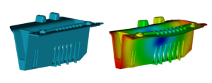
Although the default warpage result plots in Moldflow can be insightful to understand trends of how a part warps, using additional result plots can help to see the whole story of the deflection of the part in order to approach resolving out-of-tolerance warpage. Part warpage can be caused by 3 main categories, all of which Moldflow Insight can solve for. As mentioned within the shrinkage section above, the advanced warpage result plots can be enabled prior to running a Warp analysis by selecting the “Isolate cause of warpage” option. Once the simulation completes, the result plots for warpage caused by either, “Differential Shrinkage”, “Differential Cooling”, or “Orientation Effects”, can be reviewed. These help direct the analyst to the main source of deflection. Additionally, the default result plots such as Volumetric Shrinkage and Part Temperature plots can help shed insight into the causes of warpage.
How to address reducing part warpage:
While reviewing the result plots for deflection within Moldflow, the best approach to reducing warpage is to identify the main cause for deflection to address those first, then rerun the deflection analysis to see how those changes effect the other warpage plots.
Read more about warpage in injection molding: Technical Article: The Causes of Warpage.
Sink Mark Evaluation:
Analysis requirement:
Fill+Pack+Warp
What to look for within the simulation:
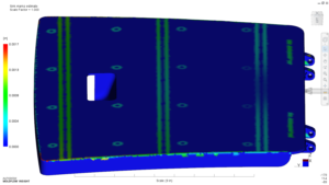
Moldflow’s sink mark result helps to identify potential part design or processing concerns by predicting the behavior of the material opposite to a part feature, such as a rib. There are built-in sink-mark results (Sink Mark, Estimate; Sink Mark Index, Sink Mark, Depth) that can be reviewed for the probability of the sink mark occurring and the depth at which it will be.
For areas that may not be captured through the built-in sink mark results (thick regions and other non-rib related areas), the use of other Moldflow results can provide insight to problematic areas. One example is the use of the Volumetric Shrinkage result, as observing shrinkage differences within those areas can lend hints to voids or sink marks.
How to approach resolving sink marks:
Optimizing packing profiles may help to reduce or even eliminate sink marks that are a result of insufficient packing. A virtual design of experiments (DOE) study within Moldflow Insight can be used to identify if packing pressure can resolve the sink marks (select sink marks as a quality criteria factor during set-up). Including melt and mold temperatures in the DOE is helpful also, as some temperatures may affect the surface strength for the sink marks.
If optimizing the packing pressure does not suppress the sink mark defects, more costly (and time-consuming) tooling modifications may need taken in order to achieve an acceptable appearance. When this is the case, simulating the following options within Moldflow Insight is ideal verses jumping right into a tool modification that may fix it, but it might also result in additional problems that would need addressed:
-
- Optimize runner system and design: If the gate is unable to stay open long enough to pack the part (the gate is freezing early), increasing the size of the gate or runners may help. This is typically a quick tool fix if it is confirmed to show improvements when reviewing it within the simulation.
- Relocate gate: Gates should be positioned from thick to thin, so if the area that shows sink marks is thicker than surrounding regions, consider relocating to gate to there (if possible). This would be a much more invasive tool modification that could cost several days (if not weeks) delay to the production timeline, thus it is highly recommended to simulate first to understand what the gate relocation would change in other aspects of part quality as well as sink marks.
- Material change: Although the switch to another material can introduce added tool work, alternate material could provide wider processing windows and different flow characteristics to the original material. Simulating a material change allows an understanding of if the existing tool geometry (steel safe areas) will work for the new material, or if changes are needed to the cavities, runners, and gates. Every material can perform differently, this includes different grades of the same material.
- Part modification: Reducing thick regions of the part can allow those problematic regions to pack better. Using a parametric study or Design of Experiments (DOE) within Moldflow Insight allows for several test simulations to be quickly set-up, and then run in a batch to compare with one another. The results of those analyses provide visual comparisons showing things like the maximum thickness a rib can be to produce an in-tolerance surface appearance (sink mark), all while incorporating process settings to show the ranges the mold must be run at to achieve those.
Read more about sink marks in injection molding: Technical eBook: Missing the Mark.

(0)