In the past, complex 3D cooling analyses, such as conformal cooling and rapid heating and cooling, have used Moldflow’s Finite Element Meshing (FEM) solvers to mesh cooling channels. This technology originated from a link to Autodesk CFD software, where CFD would mesh the channels, then Moldflow would incorporate those meshed channels into it’s simulation to use toward thermal calculations.
Although this FEM method is accurate, there are instances where those meshers may not work as expected, resulting in failure to mesh or slow solve times. As channel designs get more and more complex, the need to create a more robust meshing solver was identified by the Moldflow development team, thus the incorporation of the Voxel solver option within Moldflow Insight 2019.
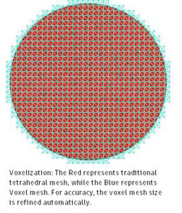
When selected to use the voxel solver, Moldflow initiates those 3D channels to be meshed into voxels, or cube-like shapes, rather than the FEM solver’s tetrahedral mesh. The voxel mesh is initiated in the background when the analysis runs. This means that after specifying the use of voxels in the process settings, the mesh displays in the user interface on those channels as tetrahedral elements but Moldflow Insight solvers treat those as voxel elements when the analysis solves.
Using this voxel meshing method uses highly parallelized code, providing possible speed boost for creating the mesh and solving. It also enables support for Linux systems. The results achieved by both the FEM and Voxel Solvers are the same, so the accuracy of the simulation is still achieved.
The workflow to use voxel solvers is almost identical to the traditional workflow, with the exception of manually switching from the default, FEM, solver option within the conformal cooling solver parameters.
Workflow:
- Import the 3D channel. The imported 3D channel can be more formats that can be meshed within Moldflow mesher.
- Mesh the 3D channel. The channel can be meshed with the existing method, or can also be meshed with the Moldflow standard mesher.
- Set inlet and outlet boundary conditions for 3D channels. There is no change between the existing and new solvers.
- Generate part and mold mesh.
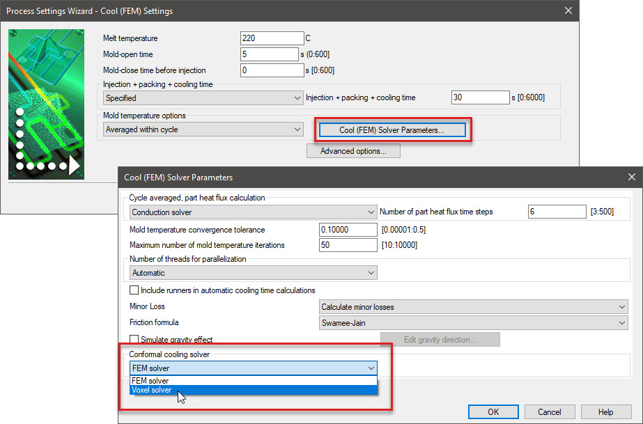
- Select conformal cooling solver. Select the Voxel Solver option under the conformal cooling solver section, within the “Cool(FEM) Solver Parameters” dialog.
- Run the analysis.

(0)