As all mold engineers know, shrinkage is an unfortunate fact of life. All plastics shrink as they cool from viscous liquids to solids, and every type of plastic shrinks in a slightly different way. And while eliminating shrinkage is impossible, minimizing it is essential for molding parts accurately.
Often, controlling shrinkage happens after the fact, when the tool is complete and parts are running. Using a combination of personal experience, educated guesswork, and trial and error, mold engineers intuit ways to change process settings enough to reduce the issue.
This approach is proven to work, but it can be extremely time-consuming. With a more detailed understanding of shrinkage behavior, and with assistance from simulation software, mold engineers can address shrinkage earlier in the design process, save time, and improve part quality.
Five factors that influence shrinkage
Shrinkage starts at the molecular level when plastics melt and cool. For the most part, these dynamics depend on the type of material and whether any filler or fiber reinforcement is present. There are also processing and part design factors to consider.
1. Amorphous materials
In a state of equilibrium, ABS, polystyrene, polycarbonate, and other amorphous polymers have a random and entangled molecular orientation. A frequent analogy is the “bowl of spaghetti.” As these materials melt, the forces between molecules weaken and move away from each other. In addition, the shear force experienced during the injection phase causes individual molecules to uncoil and align to the direction of flow. When flow stops, the molecules relax and return to a state of random orientation. Intermolecular forces continue to pull them closer together until the temperature drops enough to freeze them in place. These forces result in uniform shrinkage, but the relaxation effect causes significantly more contraction in the direction of flow.
2. Semi-crystalline materials
Unlike amorphous materials, semi-crystalline materials have regions of highly ordered, tightly bundled molecular structures. Instead of a bowl of spaghetti, these materials resemble springs connected by bungee cords. When they melt, the crystalline structures loosen and the molecules align to the direction of flow, much like amorphous polymers. But when these materials cool, they don’t relax. Instead, they maintain their orientation in the direction of flow and the molecules begin to recrystallize, resulting in significantly higher shrinkage rates. In this case, the effect is much greater in the direction perpendicular to flow. More crystalline materials, such as polytetrafluoroethylene (PTFE), isotactic polypropylene, and high-density polyethylene, shrink even more than semi-crystalline materials. As these polymers cool, the molecules form crystalline regions. This structure allows the material to fit together more tightly, making them denser and able to shrink more.
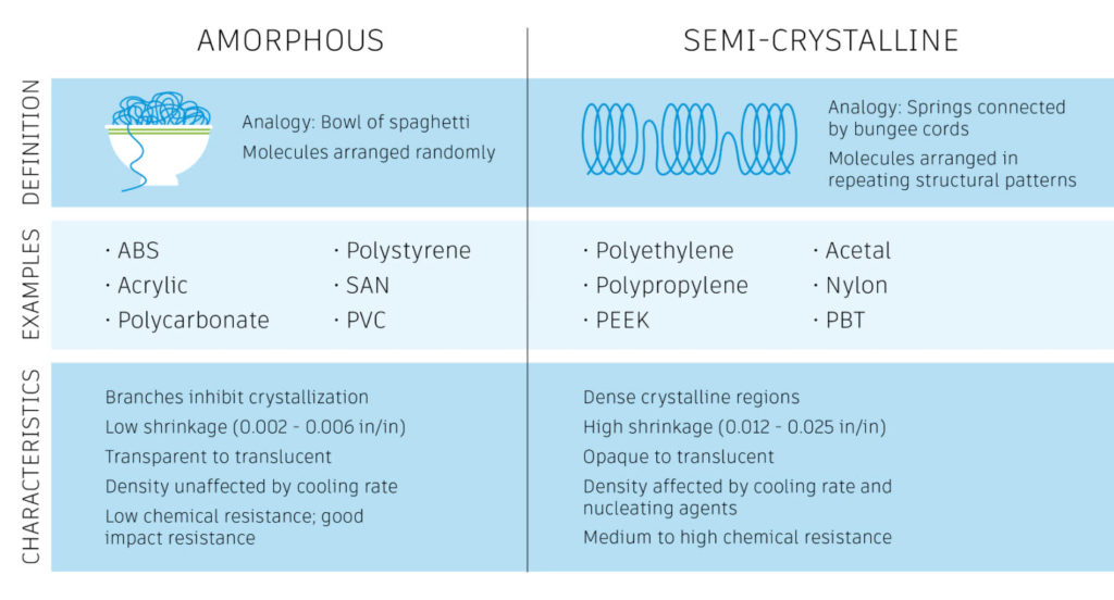
Figure 1: Crystalline and semi-crystalline materials shrink more than amorphous materials.
3. Fiber-reinforced and filled materials
When fibers are introduced into the plastic, they may counteract shrinkage effects due to molecular orientation. Fibers do not expand or contract as temperature changes, so they tend to reduce shrinkage in the direction of their orientation and increase shrinkage transverse to their orientation. Polymers filled with long glass fibers, for example, will shrink more in the cross direction than the longitudinal direction, making them unsuitable for projects with close tolerances. Resins that are filled generally shrink less than resins that are unfilled. Resins can be filled with a variety of materials, including glass fiber, wood, and mica, in order to change a part’s properties.
4. Wall thickness
Wall thickness is a factor in shrinkage because it affects the amount of crystallinity in materials, which in turn affects the total potential shrinkage. Non-uniform wall thickness causes different cooling rates throughout the part. Where walls are thinner, cooling is faster, and crystallinity and shrinkage are lower. Where walls are thicker, cooling is slower, and crystallinity and shrinkage are both higher. In amorphous materials, increasing wall thickness tends to reduce orientation effects. Maintaining uniform wall thickness helps avoid variations in shrinkage that can lead to warpage.
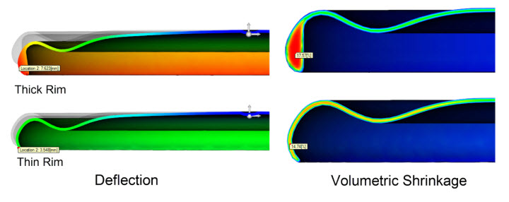
Figure 2: The thick rim experiences higher volumetric shrinkage than the thinner nominal wall. Packing the thick section efficiently is difficult due to its relative distance from the gate. The result is variations in shrinkage that cause warping.
5. Processing conditions
Adjusting processing conditions is the most familiar way for mold engineers to address shrinkage. By changing temperatures, pressures, and packing and cooling times, it is possible to mitigate shrinkage. By applying pressure to a liquid plastic, you can compress the molecules into a smaller volume and then inject more material into the mold to compensate for shrinkage. Gating from thick areas to thin areas of the part can help in this effort, providing more efficient packing for thicker sections. (By the same token, gating from thin to think will cause thin sections to freeze off first, limiting the packing of the thicker sections.) Another approach to mitigating shrinkage is speeding up the cooling rate, allowing less time for crystals to develop and increase shrinkage. One important tradeoff to note is that speeding up the cooling rate may reduce crystallinity so much that it compromises part performance. In these cases, the material loses the crystalline properties that made it an appropriate choice for the part in the first place. Non-uniform cooling can also cause variations in shrinkage and subsequent warpage, so caution should be taken to ensure cooling occurs evenly.
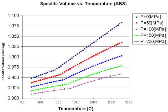
Figure 3: Pressure, volume, temperature (PVT) graphs describe how plastics contract and expand under various conditions. In general, during filling and packing, plastic contracts due to increased pressure. During cooling, plastic contracts due to decreased temperature.
Types of shrinkage
Shrinkage is typically characterized in one of two ways: volumetric or linear.
Volumetric shrinkage is caused by thermal contraction, which affects all polymers, and/or crystallization for semi-crystalline polymers. It describes the extent to which the material changes in volume as it changes from a liquid to a solid. In general, plastics can shrink up to 25% during the injection molding process. Volumetric shrinkage contracts the part in all dimensions.
Volumetric shrinkage results in well-known types of warpage. The “bowl” occurs when the perimeter has more volume, stays hotter, and shrinks more, causing the center area to pop up. The “saddle” occurs when the perimeter freezes but the center continues to shrink, pulling the perimeter in and causing it to buckle and/or twist to maintain its length.
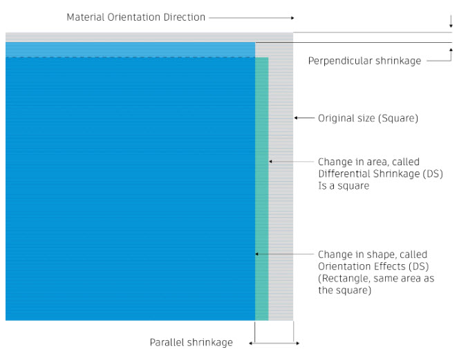
When plastics are injected into a mold, they are subjected to a new set of conditions that affect how they shrink. Specifically, shear and extensional forces act on the polymer during the filling and packing phases. Plastic molecules tend to align themselves in the direction the polymer is flowing. This alignment, or orientation, determines linear shrinkage. Orientation can vary in direction and magnitude, meaning that many polymers shrink more parallel to flow and less perpendicular to flow.
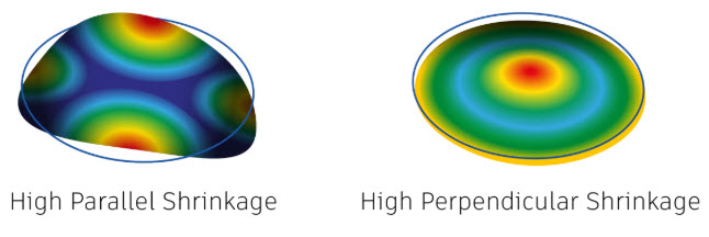
Figure 4: Orientation effects on a center gated part show the difference between high parallel shrinkage that causes a saddle (left) and high perpendicular shrinkage that causes a bowl (right).
Extensional flow
Orientation effects can align molecules in ways that are difficult to predict. In some cases, extensional forces can take over at the center of the part to align molecules perpendicular to flow. Extensional flow is an expanding flow front, or “fountain” in the center of the part that causes chains and additives to become oriented in multiple directions.
Skin laminates have no distinct orientation pattern. Outer laminates inside the frozen layer exhibit high shear rates and are oriented in the direction of flow. Transition laminates have medium shear rates, but no distinct orientation. And inner laminates have lower shear rates and tend to be oriented perpendicular or transverse to flow. The thicker the part, the more influence extensional flow tends to have. Gate type and location can also contribute to this effect.
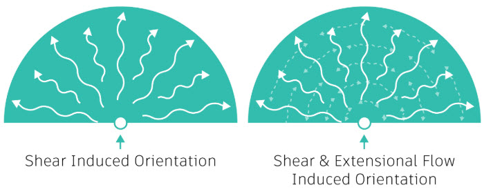
Figure 5: Compare purely shear-induced orientation effects with those caused by shear and extensional flow.
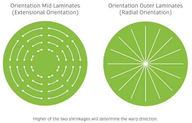
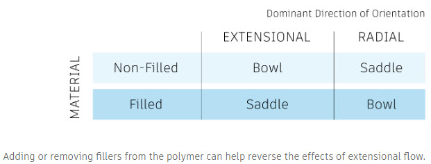
When the part exhibits both extensional orientation effects in the middle laminates and radial orientation effects in the outer laminates, whichever type of shrinkage is higher will determine the direction of warpage. This also correlates to whether the material is filled (see Figure 5).
Transient flow
Another orientation effect to be aware of is transient flow, or underflow. This refers to a flow front that changes direction during filling, typically due to a filling imbalance. The change in direction creates variations in shrinkage that create residual internal stress in the part. The greater the difference in flow between the parallel and perpendicular directions, the higher the internal stresses will be and the more warpage the part will exhibit. Another way to describe this situation is “anisotropic shrinkage,” which describes shrinkage that varies by direction, as opposed to “isotropic shrinkage” that is the same in all directions.
The difference between isotropic and anisotropic shrinkage can change the total effect of shrinkage on the shape of the part.
How simulation can help
Managing shrinkage is a complicated task, given the number of factors involved and how each one can affect the others. Simulation software can make this work easier by allowing engineers to address the problem earlier in the product design cycle.
Using simulation tools (such as Autodesk Moldflow) allows you to set up and run analyses to visualize how much shrinkage to expect, given the current part material, design, and expected processing conditions. Results can be scaled for easier interpretation. Then engineers can change the processing conditions or part design and run the simulation again to see how much shrinkage is reduced. Simulation tools also make it faster and easier to consider a wider range of potential solutions, such as changing the material or the size of the mold, all of which is more convenient than dealing with shrinkage after it has already occurred.
It’s also important to remember that shrinkage is unavoidable. However, understanding how and why plastic shrinks gives engineers an edge when trying to control its effect on a part and develop an appropriate solution that conforms with your budget and schedule.

(0)