In post 01 of this series I posed a challenging question – Have you created a sweep today? The answer is almost certainly ‘yes,’ in this post I’ll explain why.
Why is every shape is a sweep?
What do the following commands have in common?
- Extrude
- Revolve
- Coil
- Rib
- Primitives (Box, Cylinder, Sphere, Torus)
- Sweep
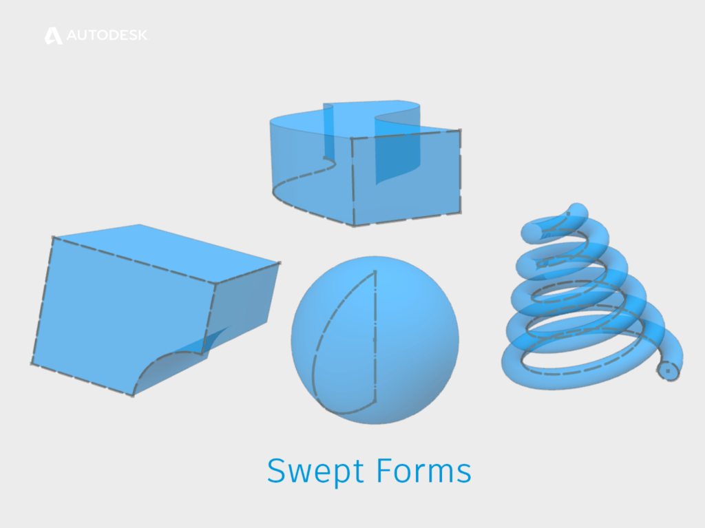
Examples of swept forms
The answer I’m looking for is that they all create features that have a consistent cross-section. This is known as ‘translation.’ The cross-section is translated along a path.
Under the hood, ASM (The Autodesk Shape Manager) uses the same algorithm to create all these features.
The difference between a sweep and the other commands is that a sweep path is explicit. We have to create it ourselves. The other commands sweep along an implied path.
For example,
- an extrude path is implied as perpendicular to the sketch plane.
- A revolve path is implied as an arc around the axis.
The path is implied by the Inventor user interface. Inventor passes the cross-section and the path to ASM which generates a 3D shape and passes it back to Inventor to display on the screen.
So – I know that you created a sweep today – even if you didn’t use the sweep tool to create it!
What can I do with a Sweep?
The one rule of sweeps is that they must have a consistent cross-section. However, we do have some additional controls for sweeps.
The cross-section can be scaled (Think ‘Taper’ in the Extrude or Sweep command). The cross-section can be rotated (Think ‘Twist’ in the sweep command).
What CAN’T I do with a Sweep?
The sweep algorithm is designed to accurately maintain a cross-section along a path, so they can only operate on one profile.
How can I sweep between multiple profiles?
Well – you can’t. At least, not with the sweep command!
If you need to create a shape using multiple profiles, you’ll need to use the Loft command (More on Lofts later).
The ‘Loft with Centreline’ command uses a hybrid algorithm that can sweep multiple profiles along a path, and ‘warp’ the shapes between the profiles at the same time.
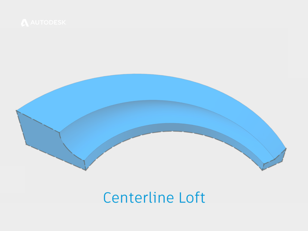
An example of a centerline loft
How does a Guide Rail Control the shape of a sweep?
Guide rails and surfaces can both be used to control the rotation (Twist) of the profile along the path.
When sweeping a guide rail, imagine lines being drawn between your path and your guide rail. As these imaginary lines rotate around the path, the profile will rotate with them.
How does a guide surface control the shape of a sweep?
A guide surface is similar, but this time the twist is about the surface normal (‘Normal’ can be thought of as perpendicular to a surface, click this link for a definition of a ‘Surface Normal’).
So – when should I use a sweep?
Because a Sweep must maintain a consistent profile, we can’t create sweeps that are curvature continuous. For this reason, it’s usually a good idea to use a swept feature (for example Extrude or revolve) as your base feature, then use the Loft command to create features that are curvature continuous with the base feature.
The secrets of Lofting | Get Smart with Inventor Part Modelling 03
Click here for part three of ‘Get Smart with Inventor Part Modelling,’ in which we will take a closer look at how Autodesk Inventor’s 3D modeling tools work under the hood, and I’ll show you how to get the best out of the Loft command.
This blog post is based on an Autodesk University class, originally by Jake Fowler and later updated by Inderjeet Wilkhu and Paul Munford. You can watch a recording of the class, and download a handout that goes with this presentation from the Autodesk University website here:
Autodesk University Online: The Inventor 7 Deadly Sins of 3D Part Modeling


