Have you ever tried to model a shape with Autodesk Inventor and failed? I have, many times!
In this post we’ll learn why Loose Tolerances aren’t helpful and bring the series to a conclusion.
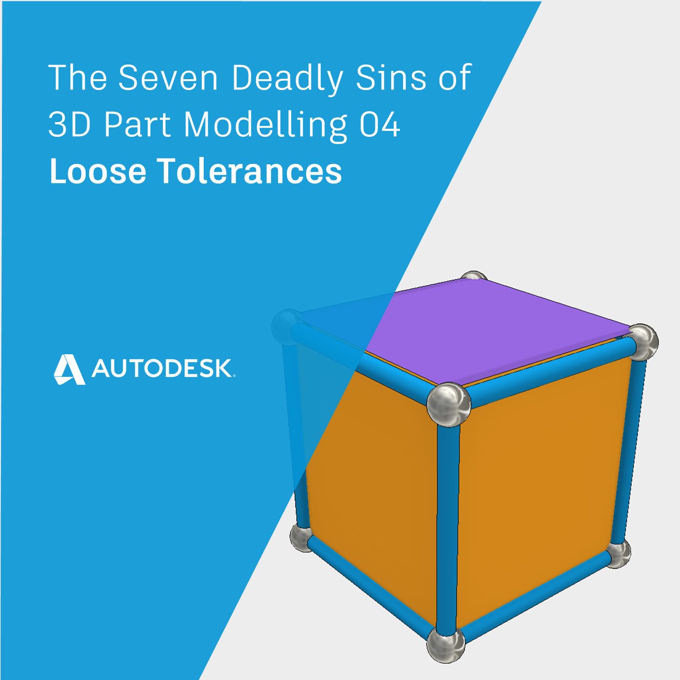
The 3D Modelling Deadly Sin of Loose Tolerances
Autodesk Inventor is a highly accurate 3D CAD modelling system. When we import files from other CAD systems that work to different tolerances, Inventor must interpolate the geometry looking for manifold conditions and meeting geometry.
For example, when we use the ‘Stitch’ command to join surfaces together, Inventor allows a tolerance. In fact, Inventor doesn’t change the underlying geometry – it uses a tolerance zone to interpolate results.
You could image this tolerance zone as a tube for edges, and a sphere for vertices.
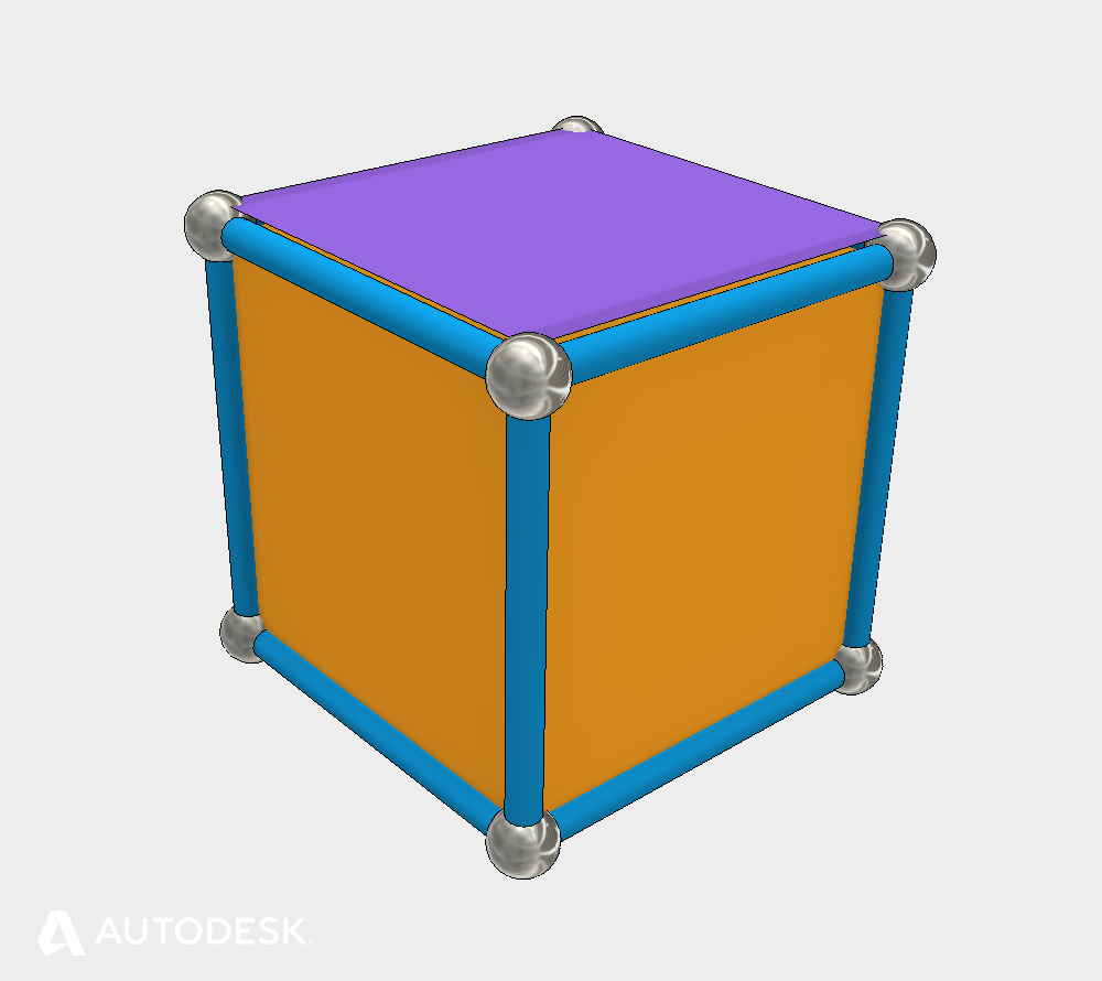
An illustration of tolerance zones
‘Loose’ tolerances could be considered geometry that shares a tolerance zone bigger than 0.1mm or 0.004in). This is not a problem in itself, but could cause problems when adding to the model downstream.
For example, thickening a face by a small distance could place a vertex outside the tolerance zone of an edge, but inside the tolerance zone of a vertex. This is likely to cause a modelling failure.
Loose tolerances are nearly always brought into Inventor from other CAD systems. If you need to allow a large tolerance to stitch surfaces together, this is an indication that you’ll have problems later. You may also see weird graphical anomalies around the problem areas where the shape delivered by ASM varies with the graphics generated to view on screen.
You can use the feedback from the stitch tool to identify edges that failed to stitch, which may need your attention.
The best solution is to return to the original CAD system, tighten up the tolerances and re-export the model. If this isn’t possible, you may have to re-build the problem surfaces in Inventor.
The Seven Deadly Sins of 3D Part Modeling – Conclusion
Now you know the 7 deadly sins of 3D part modelling and how to avoid them. They are:
- High Curvature
- Near Tangency
- Near Coincidence
- Sliver Faces
- Singularities
- Non-Manifold topology
- Loose Tolerances (This post).
We can summarize these conditions with the following:
Avoid teeny tiny ambiguous features.
Maintain manifold Topology.
Get Smart with Inventor Part Modelling and the Seven Deadly Sins.
I hope that you found this series of posts helpful in understanding why Inventor works the way it does, and how you can get the best out of it. Click the links below to continue learning!
- Click here to read ‘High Curvature and Near Tangency | The Seven Deadly Sins of 3D Part Modeling 01’
- Click here to read ‘3D Modelling Terminology | Get Smart with Inventor Part Modeling 01’
If you’d like more information on this topic – please watch the Autodesk University class recording (Link below, it’s free to watch!) and download the comprehensive handout that goes with the class.
This blog post is based on an Autodesk University class, originally by Jake Fowler and later updated by Inderjeet Wilkhu and Paul Munford. You can watch a recording of the class, and download a handout that goes with this presentation from the Autodesk University website here:
Autodesk University Online: The Inventor 7 Deadly Sins of 3D Part Modeling


Add comment
Connect with: Log in
There are no comments