Have you ever tried to model a shape with Autodesk Inventor and failed? I have, many times!
In our previous post series ‘Get Smart With Inventor Modelling’ we learned how Inventor’s modelling kernel, Autodesk Shape Manager (ASM) creates the shapes we want to see on screen.
In this series of four blog posts, we’ll discover the seven most common causes of modelling failures in Autodesk Inventor and learn techniques for fixing (or avoiding!) the problem.
The 3D Modelling Deadly Sin of High Curvature
‘Curvature’ is a measure of how much some geometry bends. A straight line has zero curvature. A sharp radius has high curvature.
Geometry with high curvature isn’t a problem, but it can cause problems downstream.
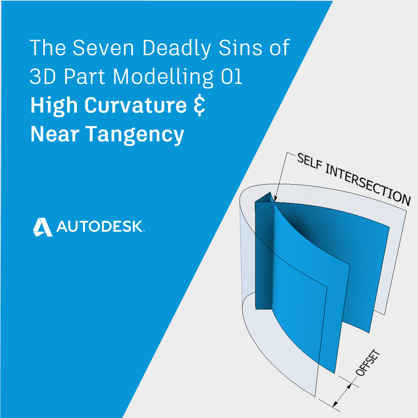
For example, if we offset from a surface which has high curvature, our new surface may include self-intersections.
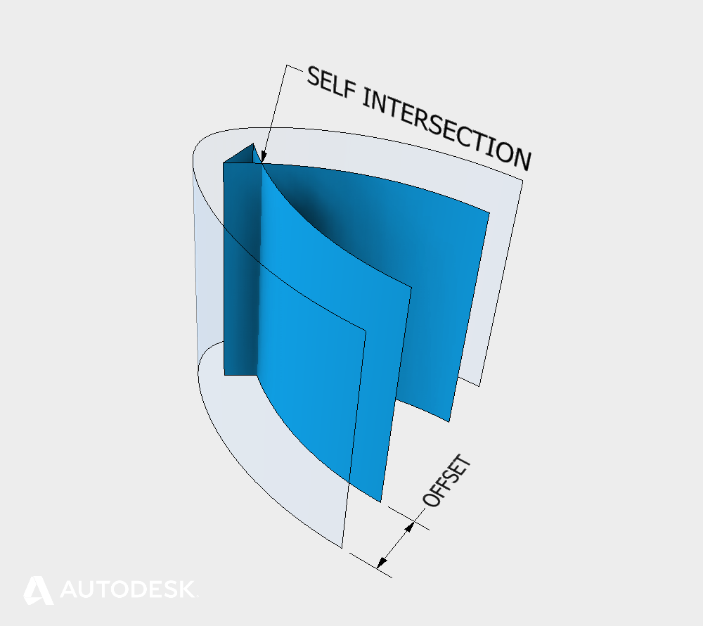
High curvature causing Self intersecting geometry
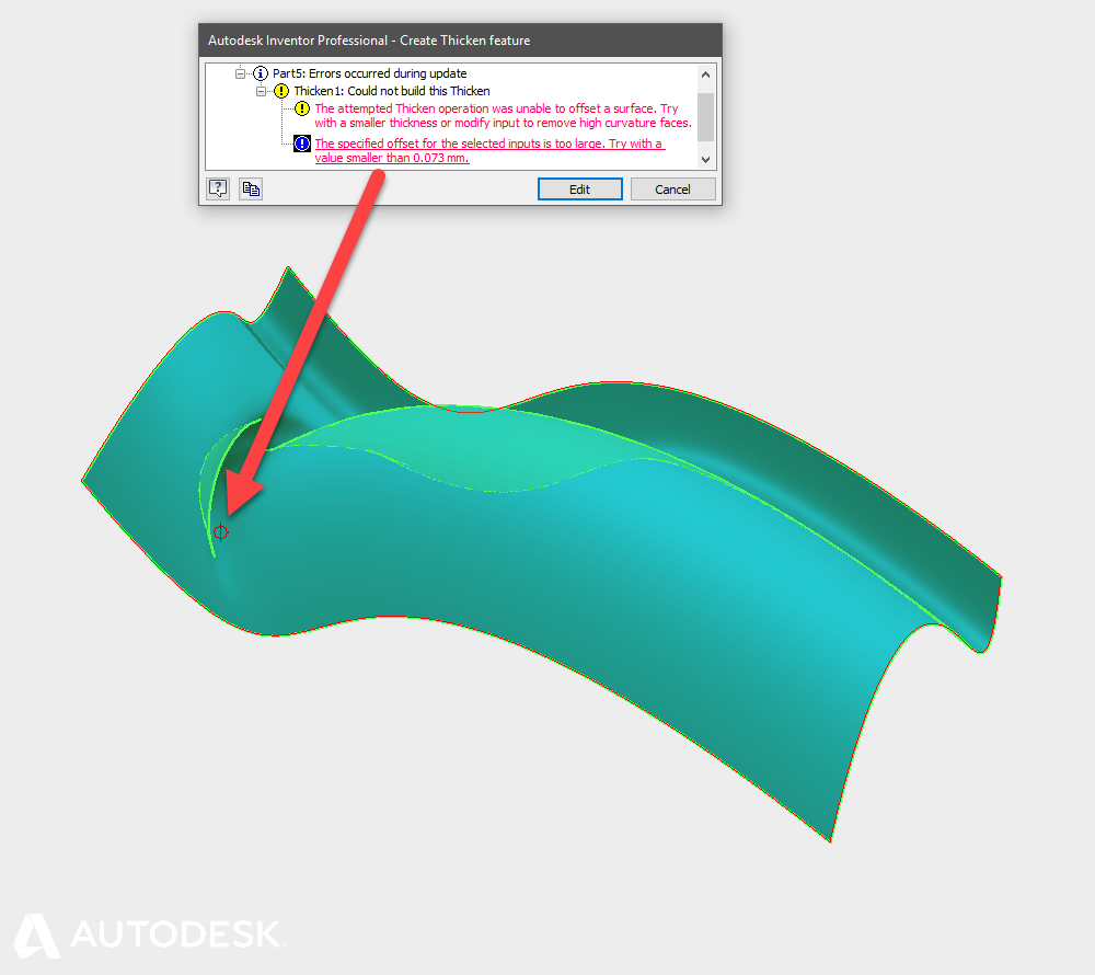
Some modelling operations can cope with self-intersections (e.g. Offset & Fillet) but some don’t (e.g. Sweep).
Self-intersecting geometry failures can be identified in the error dialog by expanding the error messages until you see the red text. Click on the red text for feedback and an indicator of where the problem is.
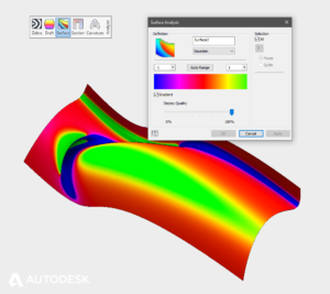
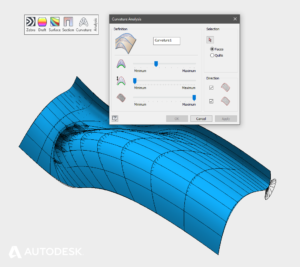
Diagnosing an area of high curvature
High curvature areas of a surface can be found with the curvature analysis or comb analysis tools.
If you can’t edit the existing geometry to remove high curvature from the input surface, you may need to work around the problem and approximate the self-intersecting area.
The 3D Modelling Deadly Sin of Near Tangency
Two adjacent faces are tangent continuous when they meet and follow the same curvature. Mathematically, the normal directions at both edges match. (Click here for a more detailed description of curvature continuity)
If the normal directions don’t match, and the discrepancy is small, the relationship is ‘Near Tangent’.
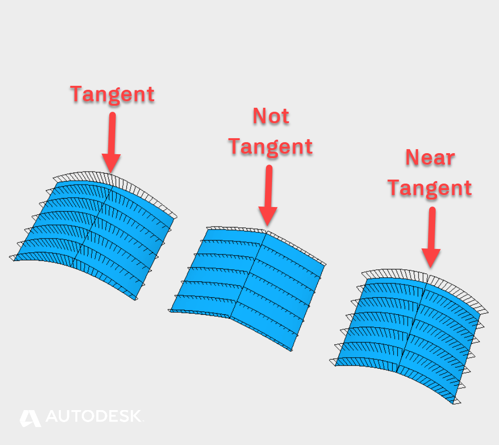
Examples of Tangent and Near Tangent faces
This can cause a problem because Inventor uses different algorithms for tangent and non-tangent surfaces. Near tangency can cause Inventor to choose the wrong algorithm – or at least, not the one you expected.
Near Tangent problems are often built into the design at sketch or feature level. If you are suffering from near tangency, check that your sketch constraints are ‘Tangent’ or ‘Smooth’. If you’ve been using Lofts or Patches, check that the edge conditions are set to ‘Tangent (G1)’ or ‘Smooth(G2)’.
To diagnose near tangency, click on the edge in question. If the in-canvas menu offers you the fillet option – the two surfaces are not tangent.
Tip: Use the fillet command with select mode Edge/Loop/Feature or ‘All Fillets’, ‘All rounds’ to analysis multiple edges at once. Edges that show up in the Fillet preview are not tangent.
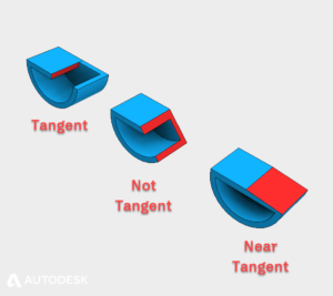
Tangent and near tangent conditions
To fix a near tangency problem, correct the underlying geometry of you can. If you are working with an imported file, try to re-export the file with higher tolerances for tangency, or re-build the offending blends inside Inventor.
Near Coincidence and Sliver Faces | The Seven Deadly Sins of 3D Part Modelling 02
This blog post is based on an Autodesk University class, originally by Jake Fowler and later updated by Inderjeet Wilkhu and Paul Munford. You can watch a recording of the class, and download a handout that goes with this presentation from the Autodesk University website here:
Autodesk University Online: The Inventor 7 Deadly Sins of 3D Part Modeling


Add comment
Connect with: Log in
There are no comments