Have you ever tried to model a shape with Autodesk Inventor and failed? I have, many times!
In the previous post in this series, we learned about the 3D Modelling deadly sins of ‘High Curvature’ and ‘Near Tangency’, and we learned how to avoid them!
In this post we’ll learn what ‘Near Coincidence‘ means and why tiny faces and teeny overlaps can cause havoc with your 3D Models.
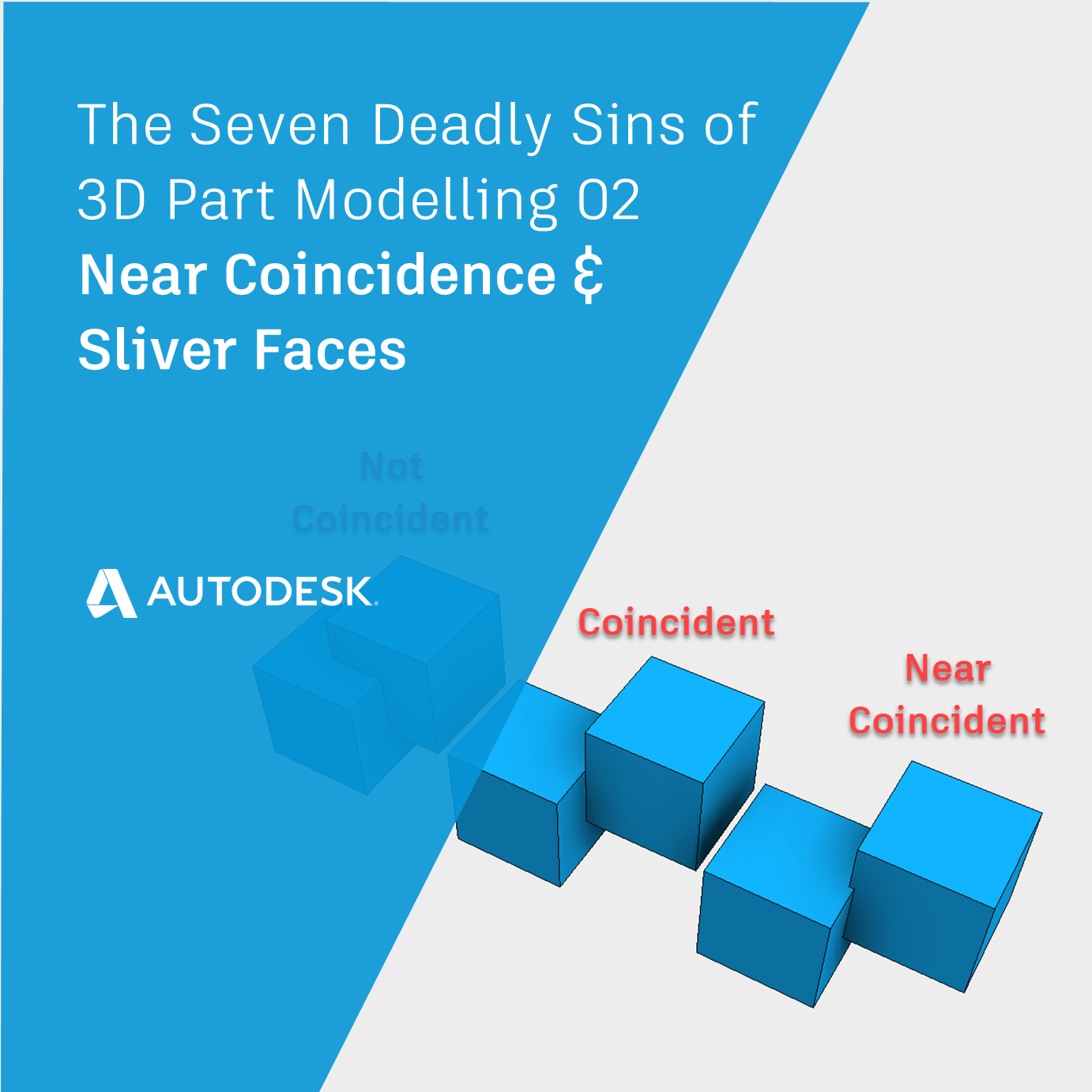
The 3D Modelling Deadly Sin of Near Coincidence
Near-coincidence occurs when two geometries overlap by a tiny amount. They are nearly the same, but not identical.
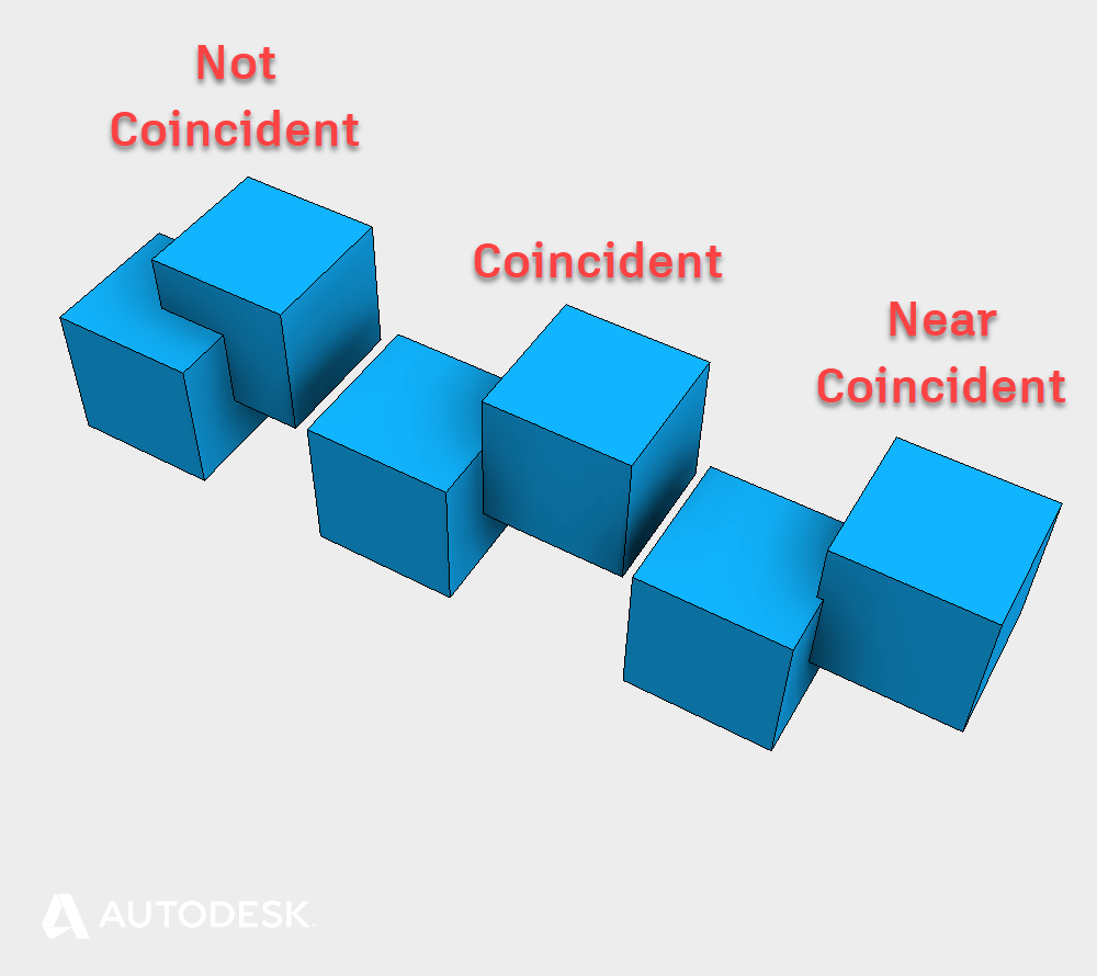
Examples of Coincidence in an Autodesk Inventor model.
This condition causes problems with downstream Boolean operations (Join, Cut, Intersect). Boolean operations calculate the intersections between bodies. If the intersection between bodies is very small, finding the precise intersection is difficult.
Near coincidence can accidentally be created inside Inventor, but it’s more likely to be a problem with an imported body.
If you are having problems with Boolean operations, try the Boolean operation with the ‘new Solid’ option selected. If this works – the underlying problem is likely to be near coincidence.
One workaround is to delete overlapping faces to turn your solids into surfaces, and then use the ‘Stitch’ command to connect the surfaces back up into a body.
The 3D Modelling Deadly Sin of Sliver Faces
Sliver faces are simply very small faces that are unexpected and not part of the design intent. These tiny faces are too small to be seen at the normal zoom.
Tiny Sliver faces cause problems because Inventor is trying to do very precise math in a very small area. Sliver faces can be created accidentally, but they are more likely to be seen on imported models.
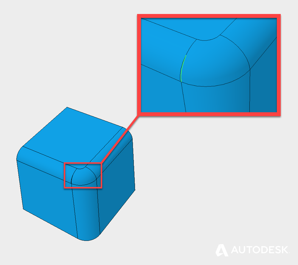
An example of a ‘Sliver face’ in an Autodesk Inventor Model
Sliver faces are very difficult to identify because you can’t usually see them with the naked eye. One method is to search for broken edges, by selecting edges in the problem area.
Sliver faces are usually quite easy to deal with once you track them down. If you can’t go back and fix the inputs to eliminate the Sliver faces, use the ‘Delete face’ tool, with the ‘Heal’ option turned on which will remove the Sliver face and re-intersect the surrounding geometry.
Singularities and Non-Manifold Topology | The Seven Deadly Sins of 3D Part Modeling 03
This blog post is based on an Autodesk University class, originally by Jake Fowler and later updated by Inderjeet Wilkhu and Paul Munford. You can watch a recording of the class, and download a handout that goes with this presentation from the Autodesk University website here:
Autodesk University Online: The Inventor 7 Deadly Sins of 3D Part Modeling


Add comment
Connect with: Log in
There are no comments