Seven tips to guarantee that Your Autodesk Inventor Sheet Metal models will flat pattern without errors.
‘Failure in creating a flat pattern.’ Who needs it? No one wants to create an Autodesk Inventor sheet metal part that won’t unfold!
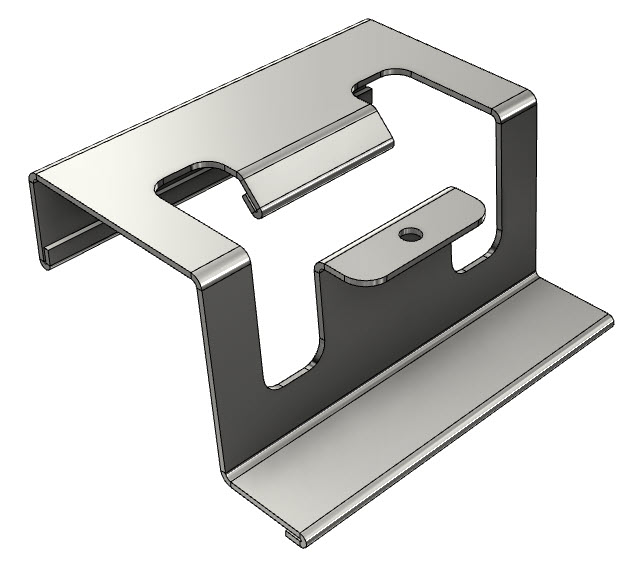
The Inventor sheet metal environment is designed to flat pattern ‘developable’ geometry. Think of the shapes you can make from a flat sheet of metal and a brake press.
Inventor will not flat pattern ‘pressed’ shapes—for example, a car door.
If you are new to modeling sheet metal components with Autodesk Inventor, click here for sheet metal modeling 101 Video.
Inventor has a dedicated modeling environment for creating sheet metal parts, and Inventor will also develop flat patterns for imported components from other CAD systems. Inventor’s Sheet metal environment is idea for machine designers.
In this blog post, I’ll give you my top seven tips for ensuring that your sheet metal parts will flat pattern every time.
‘Autodesk Inventor sheet metal flat pattern success’ was originally written for the Graitec UK blog.
#1 Model with Autodesk Inventor’s sheet metal environment
OK. This tip is kind of obvious. Creating a 3D model in the Inventor Sheet Metal environment that won’t develop is rare.
Using derived workflows (skeletal modeling) to create Sheet Metal assemblies can cause issues if you don’t pay attention.
Creating multi-body models directly in the sheet metal environment is a cleaner workflow because you have all the sheet metal tools and styles available.
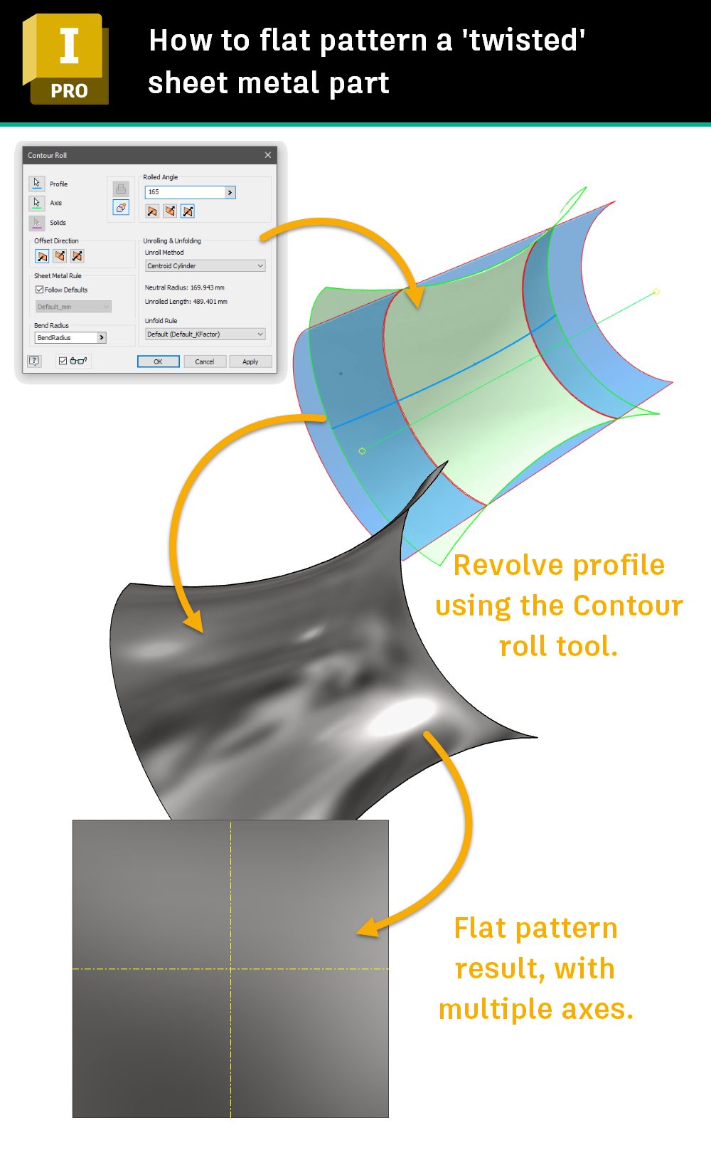
Some imported geometry contains forms that won’t develop. However, you may be able to model them Inventor’s sheet metal environment. Check out this image of a ‘twisted’ component built with Inventor’s sheet metal contour roll tool.
Use the Sheet metal tools to model your Sheet Metal parts if you can. If you can’t, check out the tips below.
#2 Leave a gap
Your model cannot be completely continuous. Make sure you leave a gap to allow unfolding.
Inventor’s ‘Rip’ tool can add a gap to parts that don’t have one.

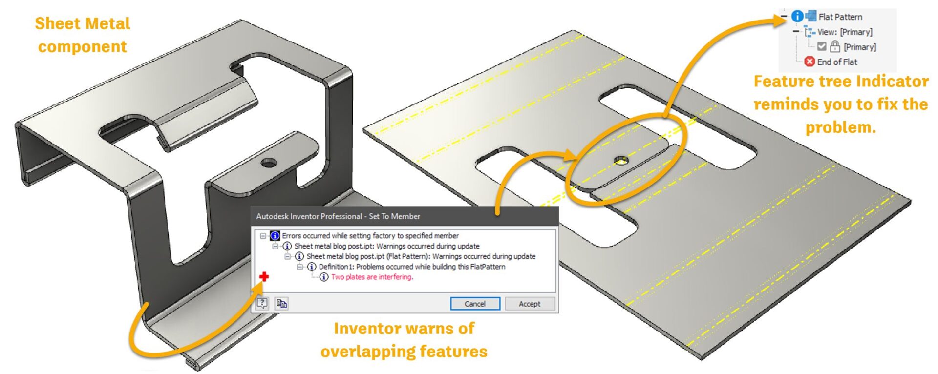
#3 No overlapping folds
The Autodesk Inventor Sheet Metal environment has a great tool for detecting overlapping folds.
Although you can develop a flat pattern with overlapping folds, Inventor will complain about it and won’t stop complaining until you fix it!
If you are using the Sheet Metal environment, you can adjust your flanges to prevent to prevent the overlap.
If you are working with imported files, you could use Autodesk Inventors direct modeling tools to fix the problem features.
#4 Consistent Thickness
To develop a flat pattern, Autodesk Inventor must start with a model that has a consistent thickness—just like a sheet of metal in real life.
This issue often arises when you build a ‘master’ component, split it up, and derive the bodies into Sheet Metal parts.
My top tip for this workflow is to model using surfaces and then use the thicken command in the part modeling environment to model a solid with a constant thickness.
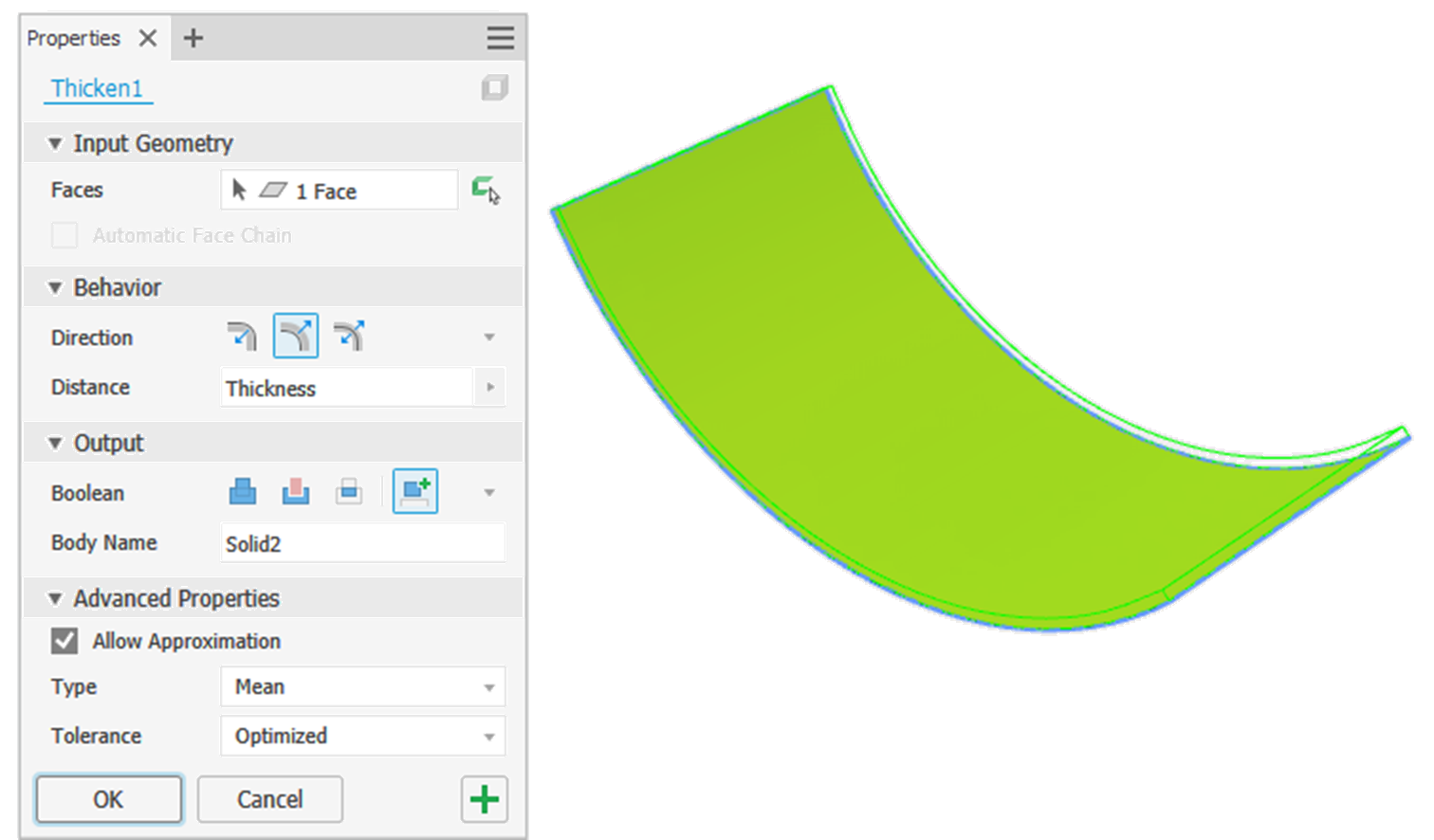
You can thicken the surface in the Multibody part and derive the body into a sheet metal part, or derive the surface into a Sheet Metal part and then Thicken in the Sheet Metal part file.
Note: The thickness of your model must be the same as the value of the sheet metal Thickness parameter of the current sheet metal style you are using.
When importing models to the Sheet Metal environment, Inventor will try to guess the thickness of an imported component. To set this manually, measure your part’s thickness and then override the Sheet Metal ‘Thickness’ parameter in the Active Sheet Metal Style to match the thickness of your imported model.
#5 Perpendicular edges

Inventor doesn’t like developing flat patterns of parts that have wobbly edges!
Use the Thicken tool to build your model from surfaces to ensure that your model’s edges are perpendicular to the face.
When building Sheet metal components, make sure your cuts are perpendicular to your faces using the options available in the cut tool’s dialog box.
One tip to ensure cuts have perpendicular edges is to use the split face tool and then the Thicken tool—referencing the sheet metal ‘Thickness’ Parameter to remove the unrequired section (See image).

#6 External fillets
Inventor won’t develop parts that have folds with 90-degree external edges.
Inventor will develop flat patterns from components with folds with 0-degree internal edges, but the external edge of the fold must have a radius.
Zero-degree internal corners were added for customers using Inventor’s Sheet Metal tools to develop designs from material such as cardboard that ‘crush’ a lot more on the internal edges than Steel does.
#7 Developable Surfaces
To flat pattern a Sheet Metal component, your design must be ‘Developable’.
A developable surface is a single curved surface that can be flattened without distortion.
A developable surface will always be a ‘ruled surface’. A ruled surface is a surface on which you could hold a rule at any point, and by twisting the rule, find a direction where the rule would touch the surface, all along its straight edge.
However – a Ruled surface is not always a Developable surface, such as in the case of a double-ruled Hyperboloid.
Developable surfaces include planes, cylinders, and cones. Non-developable surfaces, such as spheres and nurbs surfaces, have compound curves.
Here’s a really good post by Gaetan Kolher that shows the difference.
Autodesk Inventor Sheet metal modeling tips
If Inventor has trouble flat patterning a part, select a face on the part before you use the flat pattern tool. The ‘A’ side tool is equivalent to making this section permanent.
Use the sheet metal bend tool to add bends to square corners. Right-click on a bend and edit it to turn it into a corner.
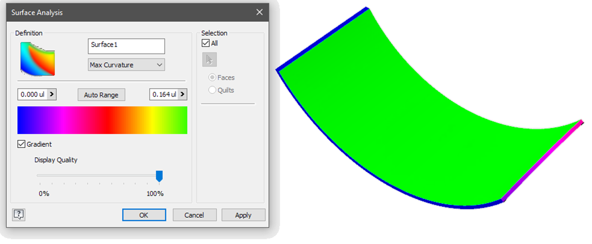
If you have imported a component from another software package and you are really struggling to get a flat pattern, use Inventor’s curvature inspection tools to look for areas that are not flat, faces that are not parallel (Equal thickness), or edges that are not perpendicular to the faces.
Check out this article by Mike Thomas for more tips on working with imported files in the Sheet metal modeling environment.
10 Design tips for Sheet Metal Fabrication
Before you start modeling parts for sheet metal fabrication, talk to the fabricator to see what they can achieve for the budget you want to spend!
Here are some basic rules of thumb for sheet metal design.
- Speak to your fabricator before starting your design.
- Ensure that the thickness you define is available in the material you want!
- Allow bend relief.
- Inside bend radius equal to the material thickness (Minimum). This may need to be increased with materials like aluminum that are subject to cracking. Manufacturers typically have dies in limited sizes – so check first.
- Minimum hole diameter is equal to material thickness.
- Keep holes at least one material thickness from the edges of the part.
- Keep holes at least 3 x Material thickness away from bends to prevent the holes from becoming distorted.
- Avoid short flanges (four times material thickness)
- Maximum boss depth = three times thickness.
- The length of at least one ‘U’ channel leg must be equal to or less than the internal dimension across the base of the ‘U’.


