When designing with composite laminates, an engineer has many tough questions facing them. Among them: When will the composite laminate really fail? How do I determine this?
Due to the non-homogeneous nature of composite materials, they fail in manners quite different than linear elastic, homogeneous materials (metals). First, they do not break or fail in a single event. Rather, failure is a progressive, nonlinear phenomena beginning with local damage and continuing through ultimate failure.
Progressive Failure Analysis is an analysis technique that uses a stress- (or strain-) based failure criterion to predict when material failure will initiate and then will reduce the stiffness of the failed material to simulate how failure “progresses” through a structure.
With composites analysis, progressive failure can be applied using in two different methods:
Progressive Failure with Classical Lamination Theory
Classical Lamination Theory is often used with progressive failure to determine the ultimate strength of a composite laminate. The reasoning behind this is as follows. Consider a laminate with a uni-axial tensile load applied to determine the laminate strength. While a composite laminate is typically composed of multiple plies oriented in different directions, the plies that are oriented with the fibers perpendicular or rotated 90 deg. from the dload direction will typically fail first.
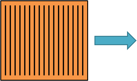
The plies that are oriented parallel to the load direction are oriented in a much stronger direction so they will not fail until a higher load level. Thus, the laminate will not ultimately fail until a higher load level.
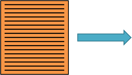
A progressive failure analysis will allow the weaker 90 deg. plies to fail first, then applying a reduction of stiffness in these plies. This reduction in stiffness will shift a higher load level to the surrounding plies to compensate for the reduction in overall stiffness which will cause these adjacent plies to fail a sooner than if there were no failures. This will continue to occur until the strongest plies, those oriented with the load direction (0 deg. plies), will finally fail and the laminate will not be able to support an increase in load. At this point, the laminate has ultimately failed.
Progressive Failure with Finite Element Analysis
In an FEA simulation, material properties are assigned to elements that compose a mesh of a composite structure. The stress and strain values that are calculated in an element due to a load being applied to the finite element mesh are determined at what are referred to as the integration points of an element, so the material properties can be thought of as assigned to these integration points as well. Note that this assumes an element that represents an individual composite ply. (“Layered elements” work slightly differently; I’ll save that discussion for a separate blog post.)
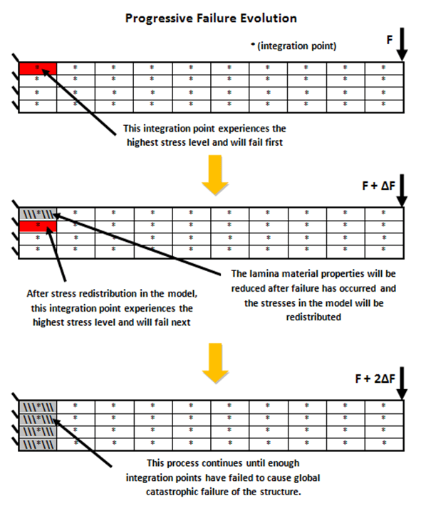
A finite element analysis will calculate the stresses in each element in the model. Using a failure criterion, the element with the combination of stresses that results in the highest failure index will be identified. With a progressive failure analysis, this element with the highest failure index will be the first element to “fail”. When an element fails, the stiffness of the material is reduced at the integration point of that element and therefore the element is “weakened”. A weakened element will not be able to carry the same amount of load as the unfailed element surrounding it, so the the internal loads in the finite element model will be redistributed around the weakened element into the full stiffness elements. This will in turn cause the elements to have a higher load than they would if an adjacent element would not have failed, and will in turn cause these new elements to fail. This process continues until enough elements fail that the entire finite element structure is weakened to a point that it cannot support an increase in load.
As an example, the following diagram illustrates the progressive failure analysis of a finite element model representation of a 4 ply cantilever beam.
A progressive failure analysis with a finite element model will provide 2 important pieces of information:
- How will failure initiate and propagate through a structure?
- What is the ultimate load that a structure can support (ultimate failure load)?
Wait, there’s more…
There many other variations for determining composite failure.
Check out the article What is the Difference between First Ply Failure and Progressive Failure? in the Autodesk Knowledge Network to learn more about the difference between these methods.
This post was done in collaboration with Dan Milligan