A pair of terms that are often used in a discussion about simulation of composite parts are load control and displacement control. Both terms refer to the process of applying a load to a composite part, they differ in how the loading is defined and the failure results when nonlinearity is accounted for. Let’s first take a look at how loads are applied to a composite part using both methods:
- Load Control
Loads are applied to a composite part using a force. This force can take different forms such as concentrated forces, pressure, and stress. The idea to focus on for a load controlled analysis is that the load changes incrementally while the displacement results depend on the stiffness of the structure. - Displacement Control
Loads are applied to a composite part using a displacement. This displacement can take different forms such as displacements and strains. Opposite from a load controlled analysis, in a displacement controlled analysis, the displacement changes incrementally while the reaction force results depend on the stiffness of the structure. A reaction force is best thought of as the force necessary to apply a particular displacement.
At first look, there doesn’t seem to be a major difference between the two, and this is true for a linear analysis. However, for a nonlinear analysis, the failure results can different quite a bit. I think the best way to look at this is by examining a load-displacement curve for the part being simulated.
We’ll just focus on one form of nonlinearity for this example – a nonlinear material response that takes into account composite material failure and the reduction in stiffness of a composite material once it begins to fail. This form of nonlinearity is covered in detail in a previous post on progressive failure.
For this example, let’s look at a carbon/epoxy quasi-isotropic composite laminate loaded in tension.
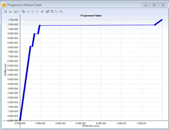
Load controlled analysis load-displacement curve. Strain is plotted on the X-axis and stress on the Y-axis. Plot generated using Helius Composite.
What we can see in the load controlled analysis is that once composite plies begin to fail, there are “jumps” in the strain of the composite coupon indicating that there are sudden displacement “jumps”. A few minor jumps occur as 90 and 45 deg. plies fail and then a very large jump when the 0 deg. plies fail.
Now let’s take the same coupon and load it using displacement control:
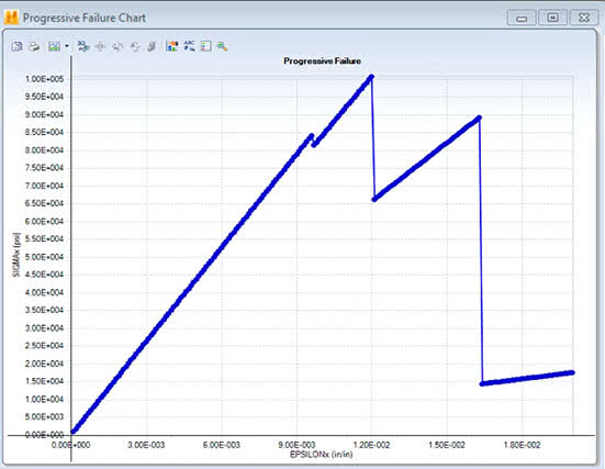
Displacement controlled analysis load-displacement curve. Strain is plotted on the X-axis and stress on the Y-axis. Plot generated using Helius Composite .
What we see using a displacement controlled loading is that this time, as plies begin to fail, there are load drops (indicated by the sudden reduction in the coupon stress level) that occur because it takes less load to displace the coupon as plies fail.
Composite coupons are typically tested using a displacement controlled method, and ultimate failure can be determined from the peak loads that are identifiable from a load-displacement curve. However, real life structures are typically loaded through loads/pressures and not through controlled displacements. Careful attention needs to be paid to what results engineers desire from their analyses to determine if load or displacement controlled loading is appropriate. When conducting a progressive failure analysis, displacement controlled loading provides a much “neater” response. Failure gradually accumulates until ultimate failure causes a large failure cascade which greatly reduces the stiffness of the structure. In a load controlled analysis, the problem can quickly become unstable as ulimate failure occurs. Even though mathematically a solution can be determined, the resulting displacements are often unrealistic.
For more information on how to generate a load-displacement curve with Helius Composite, you can visit the online user’s guide. You can also see how to create a load-displacement curve in Abaqus using Helius PFA in this online tutorial.
You may also be interested in the following composites analysis tutorials using Helius Composite:
- Computing Combined Loads
- Using Micromechanics to Determine Lamina Properties
- Bolted Connection Design
This post was done in collaboration with Dan Milligan

(0)