A major component of conducting accurate simulations of composite materials used in an increasing number of light-weight structures is gathering the required material properties to fully define the material. Often times, engineers can gather lamina (ply) material property data from suppliers of the material, but this data can be less than complete. Sometimes the data a user has access to has “holes” in it. This leaves the user unable to fully characterize a material for analysis.
This post will take a look at ways to fill those gaps.
First we’ll review a summary of the properties needed to fully define a unidirectional (UD) composite material. Then we’ll look at a couple methods for determining lamina material property values that may not be available for your UD composite. Then we’ll look at the pros and cons of using two different methods.
What are the required properties for a unidirectional composite material?
Composite materials have the unique characteristic of having different stiffness and strength values depending on direction the composite is being loaded. For UD composites, higher stiffnesses and strengths are observed in the direction parallel to the fibers as compared to perpendicular to the fiber alignment direction.
Here is the typical coordinate system used to define material properties for a UD composite. You’ll see the 1-axis aligned in the fiber direction, the 2-axis orthogonal (rotated 90 deg.) to the fiber direction in the plane of the composite ply and the 3-axis is normal to the plane of the composite ply.
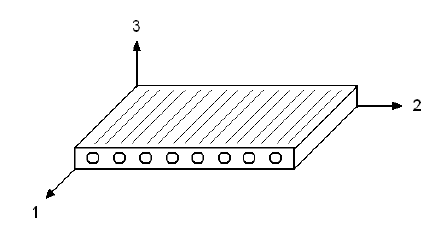
Unidirectional composites can be assumed to be transversely isotropic and are therefore fully defined by 5 material constants:
|
E11 – longitudinal elastic modulus (fiber direction) E22– transverse elastic modulus (perpendicular to fiber direction)
ν12– longitudinal Poisson ratio
G12– longitudinal shear modulus
ν23– interlaminar Poisson ratio
|
Additionally, unidirectional composites have 6 strength values that will fully define the material:
|
S11+ – tensile longitudinal strength S11–– compressive longitudinal strength S22+– tensile transverse strength S22–– compressive transverse strength S12 – in-plane longitudinal shear strength
S23 – transverse shear strength |
There are two common scenarios that are encountered when trying to fully characterize a composite material:
- Limited lamina-level material property data.
- No lamina level data, only constituent (fiber/matrix) level data.
The following will provide some methodologies to fill in these “holes”. It is noted, however, that engineering judgment should always be used when characterizing a composite material.
Scenario #1: Limited Lamina-Level Material Property Data
Often times, engineers can gather lamina (ply) material property data from suppliers of the material, but this data can be less than complete. The two most commonly missing values that prevent an engineer from fully characterizing a unidirectional composite are ν23 and S23. Steps 1 and 2 below provide recommendations for obtaining these two values. In the event that even less material data is available, Step 3 will provide sources to use to find comparable unidirectional data to use as a starting point.
Step 1: Determine ν23 if it is not provided.
The interlaminar Poisson ration is often not provided by a manufacturer. Through experience, Firehole has determined that common values for this constant are 0.5 for carbon fiber and 0.41 for glass fiber composites.
Step 2: Determine S23 if it is not provided.
The transverse shear strength is often not provided by a manufacturer. Through experience, Firehole has determined that appropriate values for this constant are obtained from the equation below:
Step 3:
Determine any remaining elastic constants/strengths by comparing the material being characterized with a similar, fully-characterized material. You can find many characterized materials in the Helius Composite material database for example. The Helius Composite data base contains many pre-defined materials that are fully referenced in the User’s Guide. Users can determine the missing elastic constants/strengths based upon the ratios evident in similar materials.
Scenario #2: No Lamina-Level Data, Only Constituent-Level (fiber/matrix) Data
Engineers also face the challenge of not having any lamina data for a unidirectional composite that they wish to use, or they have lamina data but specified at a different fiber volume fraction than the material used in their design. In this case, an analysis method commonly referred to as “micromechanics” can be used to derive lamina-level data from material properties of the fiber and matrix constituents composing the unidirectional material.
There are 2 methods available for using fiber and matrix material properties to calculate lamina level unidirectional properties – analytical calculations and simulation (FEA). Here are some pros and cons of each:
1. Analytical micromechanics calculations
Use equations to calculate lamina properties from constituent properties.
Pros
- Can be used without specialized software or a computer
Cons
- There are multiple equations for calculating lamina properties (no consensus on which equation to use)
- Not all composite lamina properties have analytical solutions
- Time consuming
- Error Prone
2. Simulation micromechanics calculations
Use finite element methods to simulate a unidirectional composite microstructure.
Pros
- Fast and efficient
- More accurate than analytical calculations
- Easy to perform design comparison studies when multiple combinations of fibers and matrix materials are being considered
Cons
- Requires specialized software
Here’s how you can use each method:
Method 1: Analytical micromechanics calculations
Using analytical micromechanics calculations to determine composite lamina properties provides many benefits to the engineer and designer:
- Predict lamina properties from a variety of matrix and fiber combinations to get the desired lamina properties.
- Lamina properties at a specified fiber volume fraction can be reverse-engineered to determine the fiber and matrix constituent properties, which in turn can be used to predict lamina properties at various levels of fiber volume fractions.
- Analytical equations provide a quick check on the accuracy of experimentally determined lamina properties.
- Money can be saved on lamina testing in initial design phase.
However, analytical micromechanics equations do have some limits:
- Poor constituent (fiber and matrix) properties will result in poor lamina predictions.
- Transverse properties of the fiber are very difficult to find.
- Predicted strengths should be considered as an upper bound as defects in the manufacture of the lamina are not taken into effect.
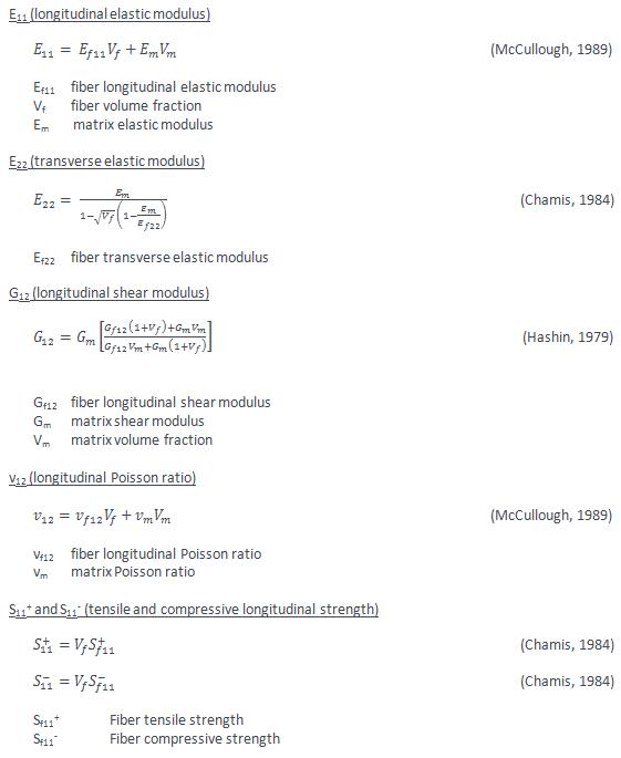
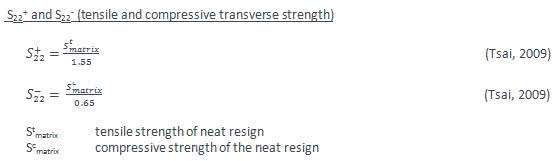
Here are the analytical equations:
Method 2: Use Helius Composite to determine lamina level material properties from the fiber and matrix properties.
Helius Composite uses micromechanics to calculate the properties of the new composite material based on known properties of the fiber and matrix constituent materials. Helius Composite’s micromechanics module utilizes a detailed finite element model of a fiber/matrix unit cell that features a uniform hexagonal distribution of parallel fibers embedded in a matrix material. The micromechanical model utilizes the properties of fiber and matrix materials specified by the user, in addition to the fiber volume fraction specified by the user (see figure). Helius Composite determines the composite material’s elastic properties (moduli and Poisson ratios) and strengths by using the micromechanical finite element model to simulate the various fundamental load/deformation relationships of the composite material.
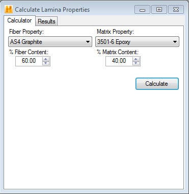
The micromechanics calculator available in Helius Composite can derive lamina properties based upon constituent properties and ratios of fiber and matrix content.
This post was done in collaboration with Dan Milligan

(0)