1 The Challenge
Until the 2025.0 release of Autodesk Netfabb Local Simulation, the only way to simulate the Directed Energy Deposition (DED) process was through detailed moving-source models. Moving-source models may be suitable for small and simple DED parts, but they can be extremely computationally intensive. For example, building a 65 mm × 65 mm × 24 mm block on a Meltio machine would require roughly 84,500 time steps to simulate with a moving-source model and the default time step settings. To further complicate matters, the plasticity algorithm may fail to converge and the mechanical model may never finish.
A new simulation method is needed to enable efficient and robust modelling of medium to large sized DED parts.
2 Methodology
2.1 Experiment
A 65 mm × 65 mm × 24 mm rectangular block is centered on a 150 mm × 200 mm × 12.5 mm Meltio M450 build plate. A laser toolpath is generated with a 45o initial angle and a 90o interlayer rotation angle. The following processing parameters are used for SAE 316L stainless steel:
- 800 W power
- r = 1 mm laser radius
- 10 mm/s scan speed
- 1.2 mm layer thickness, equivalent to nlayer = 20 layers total
- Δx = 1 mm hatch spacing
In order to allow a measurable amount of distortion to accumulate, the build plate is secured with only two bolts on the –y side of the plate.

Figure 1 Size and position of the part on the build plate

Figure 2 Laser tool path of the part on the build plate

Figure 3 Detailed view of the laser tool path, showing the 45o initial angle and 90o interlayer rotation angle.
2.2 Simulation
The 20 physical layers are grouped together into 20 simulation layer groups, i.e. 1 physical layer per simulation layer group. Other layer grouping settings can be used, but there is a tradeoff of simulation speed versus accuracy.
A PRM file is generated for SAE 316L stainless steel. Following a similar method as powder-bed part-level modelling with Netfabb Simulation, the results of the moving-source PRM generation model are mapped onto the part-level DED model for whole layer groups at a time. Simulating by layer groups drastically reduces the number of time steps compared to a moving-source model. The default *TAUT time step settings for moving-source models take one step per heat source radius motion, hence the total number of time steps ntime is given as follows:

Equation 1
Where nlayer is the number of layers, A is the average cross-sectional area of a layer, Δx is the hatch spacing, and r is the heat source radius. For the block studied here, the cross-sectional area is a uniform value A = 65 mm × 65 mm = 4225 mm2. Substituting the parameters from section 2.1 into Equation 1 yields ntime = 84,500 time steps for a moving-source model. This is a rough estimate which does not include additional time for cooling in between layers or cooling after the deposition process, but it is a lower-bound.
A cantilevered mechanical boundary condition is placed on the –y end of the build plate. The boundary conditions and mesh are shown in Figure 4.
The part-level thermo-mechanical simulation finishes 42 time steps in 8 minutes 34 seconds with 5.0 GB peak RAM usage. This is around 2000 times fewer time steps than required for a moving-source model of the same part. The maximum displacement at the end of the simulation is 5.146 mm. Simulation results are shown in Figure 5.

Figure 4 Boundary conditions shown as glyphs on the –y side of the build plate and the automatically-generated mesh

Figure 5 Simulation results with a 1x warp factor. The sub-platform is not part of the simulation, rather it is only rendered in graphical post-processing
3 DED Post-Process Measurements
The part with the geometry and processing parameters described in section 2.1 is built on a Meltio M450 machine as shown in Figure 6 and Figure 7.
After the part cools down to room temperature, a scan is performed with a FaroArm® to generate a point cloud. The experimental point cloud scan is aligned and mapped onto the simulation results in Autodesk PowerInspect. Experimental results are shown in Figure 8 and Figure 9.
PowerInspect calculates the deviation between the simulation and the scan. Out of 16 points sampled from the top of the build plate, the greatest absolute deviation is 0.265 mm, equivalent to 5.1% of the maximum simulated displacement of 5.146 mm. These deviations are shown in Figure 10.
Finally, both sets of results are extracted as shown in Figure 11 along a line on the top of the build plate at x=28 mm and plotted for comparison in Figure 12.

Figure 6 Meltio M450 in the process of depositing one of the first few layers. The two bolts securing the build plate are visible on the right side closest to the camera.

Figure 7 Final part just after the build completes in the Meltio M450

Figure 8 Experimental results (point cloud) compared with the simulation results (solid gray body)

Figure 9 Top view of the experimental results (point cloud) compared with the simulation results (solid gray body)

Figure 10 Color contour showing the deviation of the experimental point cloud with respect to the simulation results. The maximum deviation in the lower-right callout box is 0.265 mm. Note that PowerInspect uses a different coordinate system

Figure 11 A slice plane at x = 28 mm (i.e. 28 mm from the edge of the build plate). Results are extracted along the top of the build plate at this plane and plotted in Figure 12
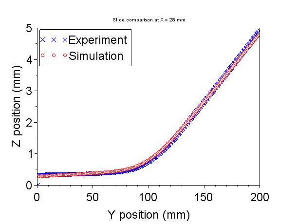
Figure 12 Z position versus Y position for a slice extracted at X = 28 mm
4 Conclusion
Multiscale DED modelling provides an accurate, computationally efficient, and numerically robust simulation method for medium to large DED parts. Predicted displacements differ by 5.1% from experimental results, proving that multiscale models are also valid for DED processes and not just powder-bed processes. The multiscale method is estimated to be roughly 2000 times faster than a moving-source model for the geometry validated here. Finally, the multiscale method decouples material nonlinearities from the part-level, guaranteeing convergence. This guarantee is in contrast to moving-source models, which may fail to finish due to non-convergence of the plasticity algorithm.

(0)