Authored By: Jeff Irwin, Principal Research Engineer, Autodesk
MPBF, which stands for metal powder bed fusion, is an additive technology accessible in Autodesk Fusion with the Manufacturing Extension and Netfabb Premium 2025. Using this tech, you can create an additive setup for supporting 3d printers, orient and arrange your parts, add support structures, and slice your models. Using Fusion or Netfabb, you can also create the additive toolpath and the machine build file, which control not only the toolpath but also important parameters such as laser speed, power, etc.
Many machine vendors have recommended settings depending on their printers and the type of metal you wish to 3d print, such as aluminum or titanium. However, it is also common practice for organizations to create custom settings to better suit their needs and produce better parts with minimized distortion due to high temperatures inherent in the metal 3d printing process.
Different techniques can be used to achieve thermal consistency through the build job. The easiest one is to decrease the build rate to enable more dwell time between layers and avoid overheating at critical areas. However, at some layers where no overheating takes place, a long waiting time in this region is a waste of time. So, a better technique is to have a variant dwell time depending on the temperature reached at each layer and increase the dwell time only when a target temperature is exceeded.
Dwell time modulation
The new *CGPT card enables the export of a temperature-controlled ghost part STL file to keep interlayer temperatures under a prescribed maximum temperature. When the part is above the target temperature, the solver will iteratively add dwell until the part is at the target temperature up to a tolerance. Once the appropriate amount of dwell is determined for each layer, a ghost part is added with a cross-sectional area such that depositing the ghost part with 0 power takes up the
necessary dwell time.
*CGPT
r1, i1, r2r1: target maximum interlayer temperature (°C)i1: maximum iterationsr2: tolerance (°C)
Example
For example, to target a temperature of 250° C, these settings can be used:
*CGPT
# Controlled Ghost ParT (this line is a comment)

# max temp (C), iterations, tolerance (C) (this line is a comment)

250.0,      5,       1.0
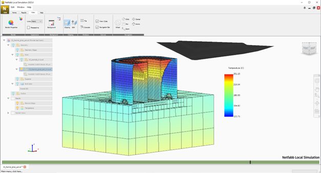
Figure 1: Ghost part created in Black at layers where the interlayer temperature exceeds the target temperature of 250 ͦ C.
The result of the simulation will be _ghost_part.stl File that can be printed together with the original part at zero power.