Five Autodesk Inventor iLogic productivity hacks for non-programmers: Configurations
Configurations in Autodesk Inventor are an awesome design workflow. They can help standardize and optimize your process, from library parts and assemblies to defeaturing designs for data exchange to the creation of design variants.
If you haven’t used Model states to configure your designs in Inventor before, check them out–they are awesome!
So, why would you use iLogic as a configuration tool? In the past, we used iLogic to compensate for the limits of iParts and iAssemblies. Model states have now overcome many of those limits, and I recommend using Model states for your day-to-day needs.
I recommend iLogic when you are building configurators that may have infinite variations that aren’t easily captured in a model state table.
A more pragmatic reason is that configurable designs are easier to ‘debug’ if I use one method to build them rather than mixing and matching different workflows such as iComponents, Model states, and iLogic.
An interesting note on how iLogic configurations work is that components that aren’t required are removed from the design rather than suppressed, so alternative components don’t appear in the BOM.
This post is one of a five-part series that provides simple examples to get you started with Inventor iLogic. In this post, we will see how to use iLogic to add and remove components from an assembly based on a parameter’s value.
This content was originally presented as a hands-on Lab at AU 2023. You can download a handout, presentation, dataset, and videos of the demonstrations from the AU class page:
IM602043-L Five Autodesk Inventor iLogic productivity hacks for non-programmers! [Lab]
Edit the iLogic rule for our configuration.
When using iLogic to configure assemblies. I prefer to build the assembly first, including all constraints and all options, before adding iLogic. This way, the iLogic rule engine will capture the design intent, meaning less code writing for us.
The dataset was prepared for this exercise, and a basic iLogic rule was created.
If you want to follow along, click here to download the example dataset and demo video
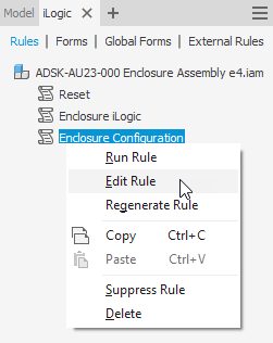
- Navigate to the iLogic browser > Rules Tab.
- Find the rule named Enclosure Configuration.
- Hover your cursor over the ‘Enclosure Configuration’ rule, RMB click, and choose Edit Rule from the flyout.
The Rule editor will open. Note that an ‘If’ statement and some comments have already been added. For the purposes of this blog post, delete them and copy and paste this code into the iLogic rule editor.
Download the class handout for details on how the code is created automagically using the iLogic rule editor.
‘Monitor the ‘Configuration’ User Parameter
‘If the value of the Configuration parameter is ‘BLUE’
IfConfiguration = "BLUE"Then
DimEnclosure_Top = Components.Add("Enclosure Top",
"ADSK-AU23-002 Enclosure Top e4.ipt")
Constraints.AddInsert("BUTTON TO TOP INSERT", "Button", "Edge0",
"Enclosure Top", "Edge1",
axesOpposed := True, lockRotation := True)
Constraints.AddInsert("TOP TO BASE INSERT", "Enclosure Top",
"Edge0", "Enclosure Base", "Edge0",
axesOpposed := True)
Constraints.AddAngle("TOP TO BASE ANGLE", "Enclosure Top", "Face0",
"Enclosure Base", "Face0", Enclosure_Angle,
AngleConstraintSolutionTypeEnum.kReferenceVectorSolution,
"Enclosure Top", "Face2")
Components.Delete("Enclosure Lid")
‘If the value of the Configuration parameter is ‘GREEN’
ElseIfConfiguration = "GREEN"Then
DimEnclosure_Lid = Components.Add("Enclosure Lid",
"ADSK-AU23-011 Enclosure Lid e4.ipt")
Constraints.AddInsert("BUTTON TO LID INSERT", "Button", "Edge0",
"Enclosure Lid", "Edge1",
axesOpposed := True, lockRotation := True)
Constraints.AddInsert("LID TO BASE INSERT", "Enclosure Lid",
"Edge2", "Enclosure Base", "Edge0",
axesOpposed := True)
Constraints.AddAngle("LID TO BASE ANGLE", "Enclosure Lid", "Face0",
"Enclosure Base", "Face0", Enclosure_Angle,
AngleConstraintSolutionTypeEnum.kReferenceVectorSolution,
"Enclosure Lid", "Face2")
Components.Delete("Enclosure Top")
EndIf
‘Update the newly inserted parts to match the assembly parameters
iLogicVb.RunRule("Enclosure iLogic")
‘Update the document
InventorVb.DocumentUpdate()
In longhand, this rule says:
Watch the user parameter called ‘Configuration’. If its value changes, immediately do the following.
If the value changes to “BLUE”, then, add the Blue enclosure .ipt, including all constraints, and remove the Green enclosure .ipt
If the value changes to “GREEN”, then, add the Green enclosure .ipt, including all constraints, and remove the Blue enclosure .ipt
Then, update the assembly (the same as clicking the Update Button ‘Lightning’).
What does this line of iLogic code do?
‘Update the newly inserted parts to match the assembly parameters
iLogicVb.RunRule("Enclosure iLogic")
This line of code runs the iLogic rule called ‘Enclosure logic.’ The ‘Enclosure Logic’ Rule maps the values of the Assembly level parameters, down to the part level parameters. This allows us to simultaneously change the dimensions of all the parts, also called ‘Top Down’ editing (click here for more information on top-down design with iLogic).
Why do we need to run this iLogic rule now?
When components are removed from the assembly, they won’t be updated by the ‘Enclosure Logic’ rule. The assembly level parameter values may have changed, and the removed component will be out of date.
Running the ‘Enclosure Logic’ rule now updates the newly inserted component to ensure its parameter values match the assembly-level parameter values.
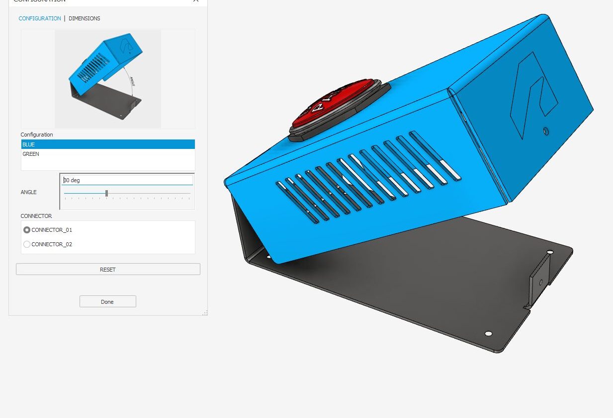
Testing the iLogic Rule
In the parameters manager, user parameter section, find the Configuration parameter, and from the drop-down list, change the value from “BLUE” to “GREEN”, and back.
You should see the enclosure lid change from the blue design to the green design and back.
Note that the constraints for each component are also deleted or added as the parameter value changes.
Tip: iLogic forms and rules are typically saved in the file you are working in, meaning the changes you’ve made aren’t saved until you save the open file. When working on your own iLogic projects, save your files regularly to save the changes to your iLogic Rules and Forms—or explore external Rules.
That was fun! What can I learn about iLogic next?
There are five block posts in this series. Read them all!
- Use an iLogic form to communicate design intent.
- Create a simple iLogic rule to check data compliance.
- Use iLogic for Top-down design
- Use iLogic for Assembly configurations
- Use an iLogic form to standardize drawing title blocks.
Click here to download step-by-step instructions, dataset, and demo videos.
How can I find out more about Inventor iLogic?
AU (Autodesk University) is Autodesk’s flagship customer event, but the learning doesn’t stop when the in-person event is over. On AU Online, you can find on-demand class videos, handouts, and data sets, so you can enjoy learning from industry experts, partners, and your peers the whole year round—it’s all free, no log-in required.
To help you find the product design and engineering content you need, we’ve created a landing page that curates design and engineering content from AU specifically for you.


