Five Autodesk Inventor iLogic productivity hacks for non-programmers: Top-down modelling
In previous exercises, we’ve learned how to add an iLogic form to a parametric part to communicate design intent, and we’ve learned how to add an iLogic rule to a part file that checks our iProperties have been filled out consistently. Click here for links to the five-part series on Inventor iLogic.
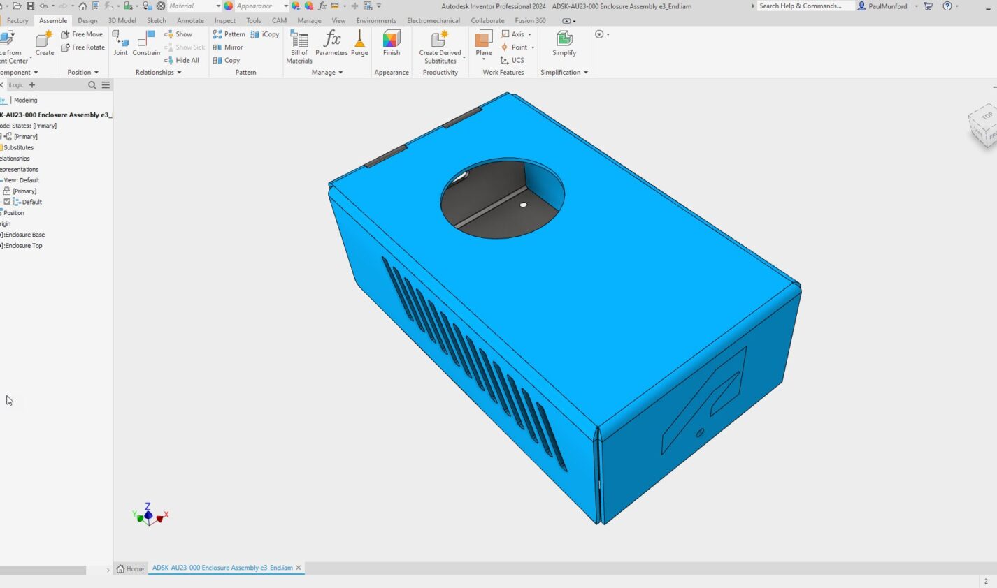
This post will show how iLogic can be used for true ‘Top-down’ design.
When learning Autodesk Inventor, many people are taught the ‘bottom-up ‘modeling technique. Each part is modeled separately and then added to an assembly file to be positioned in relation to the rest of the parts.
‘Bottom-up’ is a legitimate technique for small, simple assemblies. Imagine a Bicycle. The connections between components are standard, and it’s easy to design a push bike from a library of components.
‘Bottom-up’ can be restrictive when working on large, complex assemblies as a team. Any change to a Part must be considered in relation to all the other parts in the assembly. Components that need to be updated can be missed, causing problems down the line.
Using ‘Top-down’ design, global parameters and relationships are defined first; then, the design is divided into sections for each team, or team member. By referencing global parameters and work geometry, changes can be made to the design that update everywhere all at once.
In this context, ‘Top Down’ means that we will define the controlling parameters in the Assembly file and pass the parameter values down into the Part files. This can only be accomplished using iLogic.
This content was originally presented as a hands-on Lab at AU 2023. You can download a handout, presentation, dataset, and videos of the demonstrations from the AU class page:
IM602043-L Five Autodesk Inventor iLogic productivity hacks for non-programmers! [Lab]
Creating global parameters for top-down design with iLogic
In the example data set for this exercise, we’ve defined three user parameters, which we will reference into the parts using iLogic. They are:
- Width
- Depth
- Height
The part files in the example dataset have the same parameters with the same names and values. A handy tool to accomplish this is ‘Export and Import’ parameters to XML.
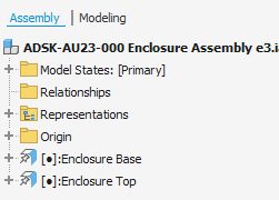
Stabilizing Browser node names when referencing components in iLogic rules.
iLogic rules use the browser node name as a shortcut to identify the components you want to work with.
When a component is placed into an assembly, the node name is automatically appended by an incremental number, for example, ‘n:5’, indicating that this is the fifth copy of this component placed into this assembly.
Let’s overwrite the node names with names of our own. Once we have written over the node name, Inventor won’t change the node name anymore. This is known as ‘Stabilizing’ the node name.
- In the model browser, Change the node name of ADSK-AU23-001 Enclosure Base e3-01:1 to Enclosure Base.
- Repeat this for ADSK-AU23-002 Enclosure Top e3-01:1, renaming it Enclosure Top.
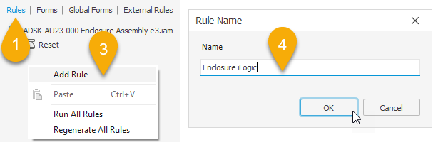
Write an iLogic rule to pass parameter values from the assembly to the parts.
- From the iLogic browser, LMB click the Rules’ tab.
- In the iLogic panel, find an empty space and RMB click.
- Choose Add Rule from the flyout.
- The Rule name dialog will open. Type ‘Enclosure iLogic’ into the input box, and LMB click the OK button to create your rule.
- The iLogic rule editor will open.
In this tutorial, I’m aiming to get you started with iLogic as quickly as possible – so I’m not going to explain the iLogic editor in depth; we’ll learn more about the iLogic Rule editor is for as we go along.
Copy and paste the following code from this blog post into the code area of the iLogic rule editor:
'Link top-level user parameters to the parts
'Enclosure Base
Parameter("Enclosure Base", "Width") = Width
Parameter("Enclosure Base", "Depth") = Depth
Parameter("Enclosure Base", "Height") = Height
Parameter("Enclosure Base", "Connector") = "CONNECTOR_01"
'Enclosure Top
Parameter("Enclosure Top", "Width") = Width
Parameter("Enclosure Top", "Depth") = Depth
Parameter("Enclosure Top", "Height") = Height
InventorVb.DocumentUpdate()
The lines beginning with an apostrophe ‘ are comments to remind us what this rule does.
The first four lines of code pass the values for the ‘Width,’ ‘Depth,’ ‘Height,’ and ‘Connector’ user parameters from the Assembly User parameters to the ‘Enclosure Base’ User parameters.
The second three lines of code pass the user parameter values from the assembly to the Enclosure top.
The final line of code is the equivalent to clicking the update button from the Inventor user interface (The button with an icon that looks like a flash of lighting).
Test the iLogic code!
This iLogic code takes the value of the assembly-level parameter and ‘pushes’ the parameter’s value down into the matching parameter of the part files.
- In the assembly, open the parameters manager.
- In the parameters manager, change the value of the Width parameter to 150mm.
- In the graphics window, watch the assembly change size… say ‘Oooooo!’.
When the value of the parameter in the assembly changes, the value in the part will also change.
This is true ‘top-down’ control of an assembly, and it can only be accomplished with iLogic.
The code reads:
Find the part with the model browser node name “Enclosure Base”. In this part, find the user parameter named “Width”.
Make the value of the part user parameter “Width” the same as the value of the user parameter in this assembly, also called “Width”.
Next, do the same for the part called “Enclosure top”.
Tip: iLogic forms and rules are typically saved in the file you are working in, meaning the changes you’ve made aren’t saved until you save the open file. When working on your own iLogic projects, save your files regularly to save the changes to your iLogic Rules and Forms—or explore external Rules.
That was fun! What can I learn about iLogic next?
There are five block posts in this series. Read them all!
- Use an iLogic form to communicate design intent.
- Create a simple iLogic rule to check data compliance.
- Use iLogic for Top-down design
- Use iLogic for Assembly configurations
- Use an iLogic form to standardize drawing title blocks.
Click here to download step-by-step instructions, dataset, and demo videos.
How can I find out more about Inventor iLogic?
AU (Autodesk University) is Autodesk’s flagship customer event, but the learning doesn’t stop when the in-person event is over. On AU Online, you can find on-demand class videos, handouts, and data sets, so you can enjoy learning from industry experts, partners, and your peers the whole year round—it’s all free, no log-in required.
To help you find the product design and engineering content you need, we’ve created a landing page that curates design and engineering content from AU specifically for you.


