When my drawing office moved from 2D CAD to 3D CAD with Autodesk Inventor, we noticed a significant upturn in productivity. Why?
AutoCAD has a single document environment. If one of your colleagues is working late on a project, it’s really hard to help them out.
Autodesk Inventor has a distributed file system. This means that we can split the work up amongst our colleagues and work in parallel on the same project.
One colleague works on these parts, one colleague works on those parts, one colleague could start putting parts into assemblies – you might even be able to start laying up drawings early in the design process.
But – for this to work, you need to be working as a team, and teams have ground rules, in this post we will take a look at the preparation you can do to set your team up for success.
Preparation – Modelling Standards
You don’t have to agree with me on standards such as parameter naming or model orientation, but you do need to follow industry standards, or at least get everyone in your office to agree to work the same way!
Here are some topics that you’ll need to consider. Please feel free to copy and paste from this section for your CAD manual.
Preparation – Orientation
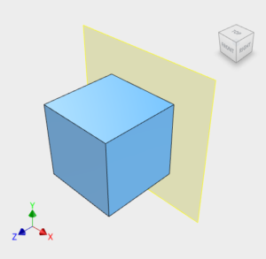 Traditionally Engineers have always drawn components from the front. This makes the coordinate system:
X = Left/Right
Y = Up/Down
Z = In/Out
This is how Inventor is set up.
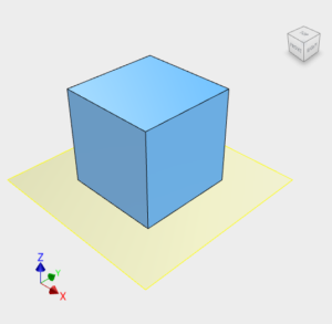 Traditionally Architects have always drawn their building layouts from the top. This makes the coordinate system:
X = Left/Right
Y = Forward/Backward
Z = Up/Down
This is how AutoCAD is set up.
Engineering = Y Up
Architecture = Z Up
If you work with AutoCAD or Revit users, or you often share files with colleagues in the Architecture/Construction, you may want to model with ‘Z up’.
You can prepare your Inventor template to use ‘Z up’ by adjusting your view cube orientation and saving your file as the ‘Standard’ template (remember to do this for Parts, Assemblies and presentations).
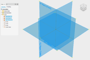
Preparation – Origin Planes
You can’t edit or delete the Origin planes, but you can re-name them. Rename the Origin planes in your template files to match your view cube orientation to subtly reinforce your modelling orientation standard.
Preparation – Parameter naming
Parameters in Inventor represent placeholders for values that can change. Parameter names must follow some rules set down by Inventor.
To improve communication between users, it’s a good idea to agree on some conventions for parameter naming.
You might also want to consider if there are any standard named parameters that should be in every model file? If so – include them in your template (and should they be set to ‘export’ so that they can be read into the BOM/Parts List?).
Shorter parameter names are easier to remember and to type as you are modelling but can get obscure. All User Parameters should have a comment, to explain their function.
Parameter naming rules:
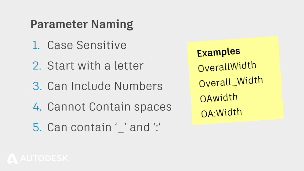
- Parameter names are case sensitive (length & LENGTH are both acceptable).
- Parameter names must start with a letter (but can include numbers).
- Parameter names cannot contain spaces.
- Parameter names can only include the Underscore ‘_’ and Colon ‘:’
Some parameter names are reserved by Inventor and cannot be used. Please see the help for details.
Tip: Don’t forget that you can rename parameters on the fly. Type the formula:
‘Parameter name = Parameter Value’
into any input box to rename the parameter as it is created.
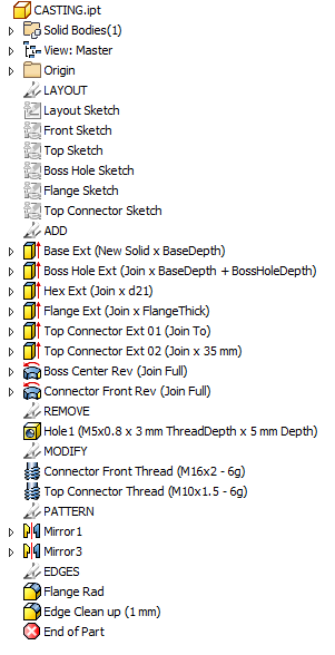 Feature Naming
If you have more than a few features, it can be difficult for the next person who opens your model to work out how the features are related.
By renaming your features, you can provide an easy ‘Breadcrumb trail’ to guide your colleagues through your model’s structure.
In preparation to start modelling, give a little thought to the features in the design. Can you give them obvious, distinct and unique names?
Remember that Inventor will not let you give two features the same name, even if those features are of different types, so append the feature name with the feature type
Example Feature suffixes:
Ext = Join Extrusion
Cut = Cut Extrusion
Rad = External Fillet (Radius)
Fil = Internal Fillet
Rev = Revolve
Mir = Mirror
Pat = Pattern

Tip: The ‘Show Extended Names’ Option will show additional information next to your features such as extrude length or Fillet Radius.
Turn on extended names, by clicking in the model browser > Hamburger menu > Display preferences > Show Extended names.
Or by visiting, Tools > Application options > Part [Tab] > ‘Display extended information after feature node name in browser’ [Check box].
Execution | Reliable Part Modelling 04
This blog post is based on an Autodesk University class, by Luke Mihelcic and Paul Munford. You can watch a recording of the class, and download a handout that goes with this presentation from the Autodesk University website here:
MFG226705: Reliable Modeling Techniques for Complex Part Design in Inventor
Edit 2020/11/24
This class was updated and repeated for Autodesk University 2020. You can find the revised version of the class, with video, handout, and dataset here:
‘Reliable Modeling Techniques for Complex Part Design in Inventor’ At AU2020
We also created a second part to the class: ‘Reliable Techniques for Complex Assembly Design in Inventor‘ – Here’s the link:
‘Reliable Techniques for Complex Assembly Design in Inventor’ at AU2020


Hi Paul. I've enjoyed your series to date. Please keep posting on this topic. Can you suggest settings in Inventor that would make it more natural to follow your guidelines? One that comes to mind is disabling the automatic hiding of consumed sketches. Subsequent sketches are more likely to be linked to sketch geometry, as opposed to feature geometry, if the previous sketches are already visible. I'm sure there are others. I look forward to your reply.
Hi Bob, That's a great tip - thanks for sharing. I have made some recommendations for application and template settings in the handout for the Autodesk University class that this blog post is cribbed from (See the link at the end of the article). Please feel free to download the handout, take a look and let me know if you have any feedback? The handout includes a copy of two checklists I created. One checklist to help CAD admin's set up templates and standardise application settings and one checklist to help CAD modellers standardise their modelling process. I hope that you find them helpful! Paul