After spending some time with the beloved classics in the previous episodes, it’s time to turn our attention to a less praised retro gem: Skate or Die. Featuring not-so-iconic characters such as Rodney Recloose and Aggro Eddie, Skate or Die was targeted to relatively older gamers. You know, teenagers who like to break stuff. And that is exactely what we are going to demonstrate here. Specifically, let’s use Autodesk Helius PFA to figure out how fast can the skater crash his board into the edge of a halfpipe without breaking it into two pieces.
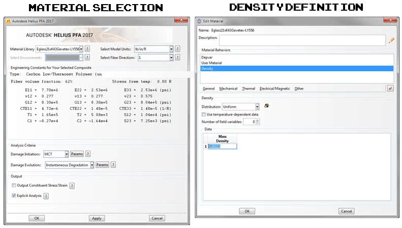
Since we are simulating a dynamic event, we will need to enlist the capabilities of an Explicit finite element solver. Helius PFA is compatible with Abaqus/Explcit so we will be using that solver. After you’ve opened Abaqus/Explicit, switch to the Property module and select Create Composite Material from the Autodesk Plug-ins toolbar. Select Eglass21xK43Gevetex-LY556 (a glass/epoxy composite) with lb/in as the units and be sure to select the Explicit Analysis checkbox. You’ll also need to define a density for this material so open the Edit Material window and enter a density of 0.00015. If you’re wondering what the units are for density, keep in mind that Abaqus is a unitless solver. For the lb/in system, the units of density turn out to be lbf s2/in4, which kinda makes my head hurt.
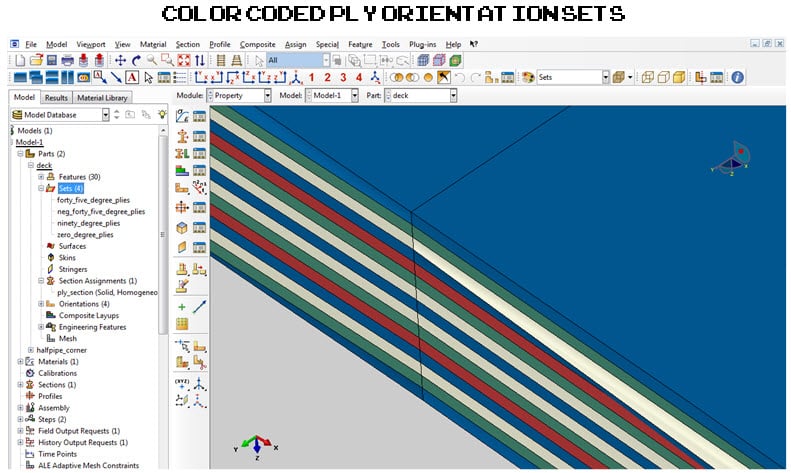
Next, create geometry sets for each ply orientation. The layup for this model is [0/45/-45/0/90/45/-45/0/-45/45/90/0/-45/45/0] so you’ll need to create 4 sets since there are 4 orientations. The long axis of the skateboard is parallel to the 0 degree fiber direction so create a datum coordinate system that is aligned with the 0 degree fiber orientation and then assign orientations for each set that you just created.
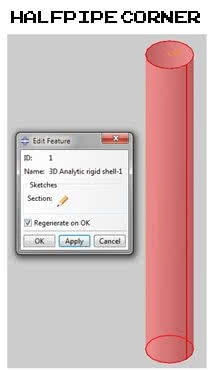
What good is a skateboard simulation without something to land on? Let’s generate a 3D analytic rigid cylinder to approximate the corner of the halfpipe so that we have something to smash the skateboard into. Give the cylinder a diamter of 2 inches and assign a reference point to it and we’re good to go.
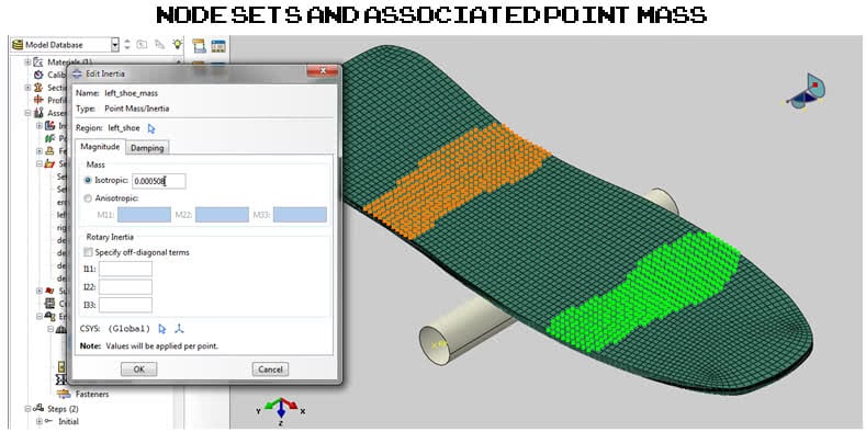
Moving on to the Assembly module, create a Dynamic, Explicit step with a time period of 0.1 seconds and position the skateboard so that it is centered 1 inch above the halfpipe corner. Now, a skateboard crashing into something is cool, but it won’t be realistic unless we add some mass to represent the rider. Start by creating node sets on the upper surface that look like left and right shoes. Then, all you need to do is assign a point mass definition to each node set. We’re going to assume the rider weighs 150 lbs and the mass of the rider is split evenly between the left and right shoes. The specific values for each node set are a function of the number of nodes in each set and when we run the numbers, we get 0.000508 for the left shoe and 0.000484 for the right shoe. If those numbers aren’t right, I’ll blame Rodney since he did the calculations.
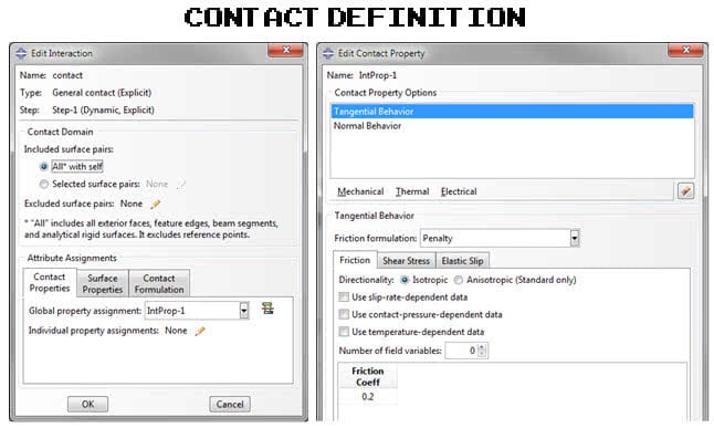
In order to get the skateboard and the halfpipe corner to interact, a contact definition needs to be created. In the Interaction module, create a General contact definition and associate it with a contact property that uses a friction coefficient of 0.2. Defining the boundary conditions are all that is left. For the halfpipe corner, grab the reference point and fix all 6 degrees of freedom. Finally, give the skateboard an initial velocity of 50 in/sec and submit the analysis to the solver.
Let’s take a look at the results! Coming in at a modest 50 in/sec, the skateboard impacts the halfpipe corner, rebounds, and lives to see another day. Strap on a helmet and crank it to 150 in/sec, however, and you’re going to have a bad time because the skateboard breaks into 2 pieces. There is always a silver lining and in this case it belongs to Rodney who will be pretty pumped when you have to pony up some cash for a new board.
That’s all for this week folks! We hope you enjoyed this episode of 8-bit simulation and if you didn’t get a chance to see the video, here’s the full workflow. Also, if you enjoyed it, feel free to share it on Facebook, Twitter or Pinterest. See you again next week for another exciting 8-bit Simulation!

(0)