The Composites Pin Board is a collection of posts covering composite engineering topics that our own technical specialists find useful or reference often. Think of it as Pinterest – for composite engineers. These articles can also be found in the Autodesk Knowledge Network.
Due to the orthotropic nature of composite materials (different properties in various directions), a Cartesian coordinate system is assigned to both composite plies and composite laminates to develop the equations for calculating how a composite material will respond to mechanical and thermal loads. The standard way of differentiating between ply values and laminate values is through the use of numbers (1, 2, and 3) for ply values and letters (x, y, and z) for laminate values.
A standard unidirectional composite ply coordinate system aligns the 1-axis with the fiber direction and the 2-axis orthogonal (rotated 90 deg.) to the fiber direction in the plane of the composite ply. The 3-axis is normal to the plane of the composite ply.
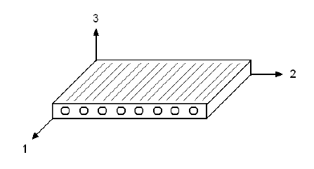
Composite ply coordinate system
A standard composite laminate coordinate system aligns the X-axis with the fiber direction of a 0 deg. ply and the Y-axis orthogonal (rotated 90 deg.) to the fiber direction of a 0 deg. ply in the plane of the composite ply. The 3-axis is normal to the plane of the composite laminate.
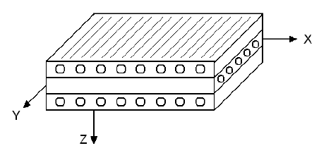
Composite laminate coordinate system (middle ply is a 0 deg. ply; top and bottom plies are 90 deg. plies)
In the development of equations for determining the structural response of composite laminates, when material properties (E, G, v, CTE, etc.) are labeled with a subscript of 1, 2, or 3, ply material properties are being indicated. When material properties are labeled with a subscript of X, Y, or Z, laminate material properties are being indicated. So E1 would be the longitudinal (fiber direction) stiffness of a composite ply while EX would be the longitudinal (fiber direction of a 0 deg. ply) stiffness of a composite laminate.
Labels on stress and strains values get a little more confusing as both numerical and alphabetical subscripts are used when indicating ply stresses and strains. The key to keep in mind is the the subscripts refer to coordinate system directions. So composite plies have both stresses and strains in the 1, 2, and 3 directions (indicating the stresses and strains aligned with ply coordinate system) and in the X, Y, and Z directions (indicating the stresses and strains alighted with the laminate coordinate system). So for example, with a 45 deg. ply, the stresses and strains in the 1 direction are in the direction of the fibers in the ply while the stresses and stains in the X direction are rotated -45 degrees from direction of the fibers in the ply.

(0)