It’s important to understand the temperature distribution throughout your assembly, especially when working with various materials, but what do you do once you have that information? One thing you can do with it is determining the resulting stress due to the temperature profile. In this post we’ll take a look at how you can take thermal results from Autodesk CFD (as seen in last week’s post) and applying them to your stress analysis in Autodesk Simulation Mechanical.
Since we already have the thermal results computed, this setup will be pretty simple. We’ll start out in Autodesk Simulation Mechanical where we will open the same .step file that was used in Autodesk CFD. It is important to use the same geometry so that you can accurately map the thermal results from one product to the next.
After opening the model, the first step is to mesh the assembly. Since this geometry was created so nicely, and is relatively simple, using the default settings is sufficient. Just press the generate mesh button and you’re all set to define the rest of the parameters
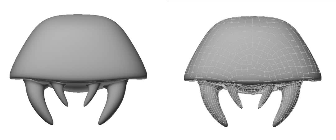
The next step is to define our materials. Much like in the previous setup, the teeth will be defined as A36 steel (so they can easily crush Samus!), the body will be Silicon, and to change it up a bit, we’ll make the internals out of quartz.
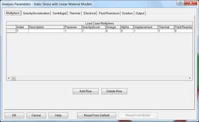
Something that is a little different in this setup is that our loads are actually doing to be defined in the Analysis Parameters instead of directly on the model. After opening the parameters, the first screen you see is the load case multipliers table. This controls what loads are active for each analysis. For this design, we’ll have to make sure there is a 1 in both the gravity/acceleration and thermal columns, activating both gravity and thermal loading conditions.
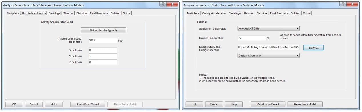
Going into the Gravity/Acceleration tab, we’re able to click the “Set for standard gravity” to define the value for your unit system. This number could be increased if you’re looking for a higher g loading. Although Metroids seem to defy gravity, we’re going to make sure it is pointing in the right direction, in this case –Y.
Now on the Thermal tab we can point the analysis to the results from the CFD analysis. For the “Source of Temperature” we will choose “Autodesk CFD file,” browse to your .cfdst file and then define which design scenario you want to use.
All that is left to do before analyzing is adding some boundary conditions. Assuming this Metroid was latched onto Samus before being frozen, we’ll select each top surface of the teeth. Applying a General Constraint, we’ll choose Fixed and press ok. Now we’re ready to press analyze and check out the results.
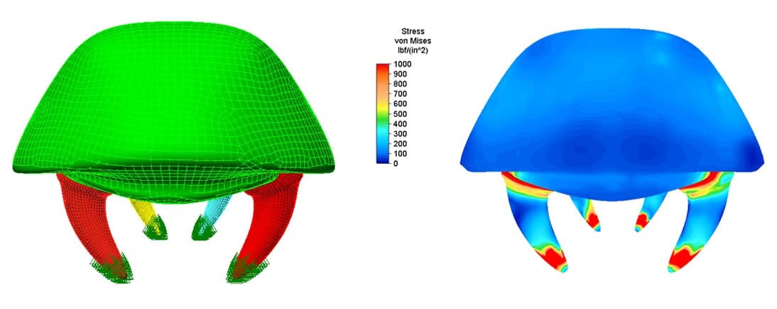
In the results, we can see that just due to freezing, the Metroid is seeing over 6,400psi of stress, primarily in the teeth. This would help explain why Samus is able to escape and destroy these things so quickly!

(0)