Let’s talk about FEA, which most of you know stands for “Finite Element Analysis”. It is the “Element” that makes it possible to analyze complex models. Simple models can be solved for stress or displacement using closed-form solutions. However, as the model becomes more complex we need to discretize the model or divide it into elements that can be solved.
In this article, we will focus some time on the mesh at a beginner to intermediate level. It’s not only important that your model meshes successfully. It’s even more important that the mesh will provide accurate results that you can use to make proper design decisions.
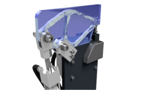
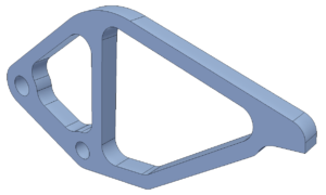
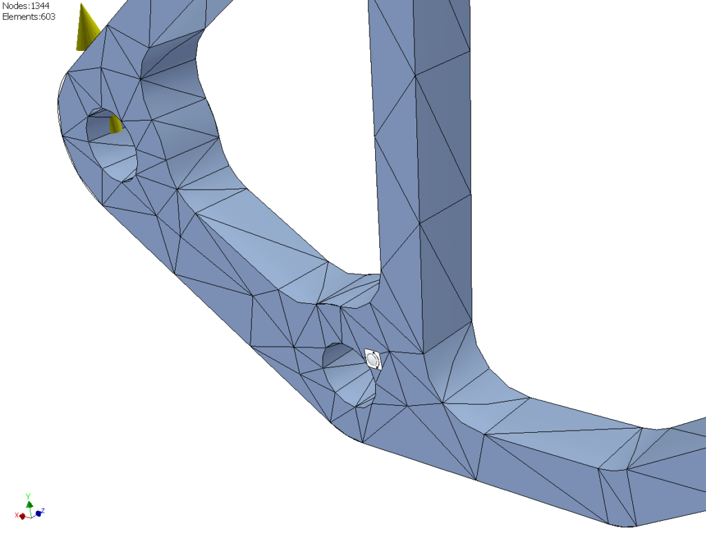
As we discuss the options available for generating the mesh, we will illustrate them using the clamp arm attached to an actuator. “Shape Generator” in Autodesk Inventor has already been used to create a lightweight design for the component.
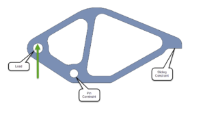
After we apply the material and boundary conditions it’s time to mesh the part. For the purposes of this article, the solid tetrahedral element will be used. There are other types we can dive into in a future segment.
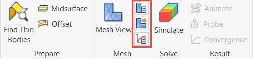
We are only going to focus on the three mesh options in the Simulation ribbon.
- Mesh Settings
- Local Mesh Control
- Convergence Settings
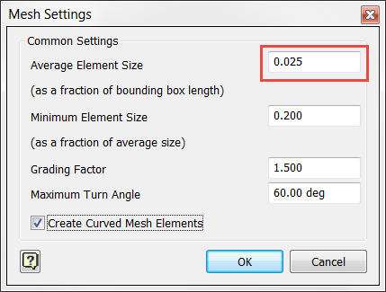
Let’s begin in the mesh settings dialog. There is a checkbox near the bottom, “Create Curved Mesh Elements”. I would recommend checking this box at all times. It will increase the solve time, but for most models the extra wait is negligible.
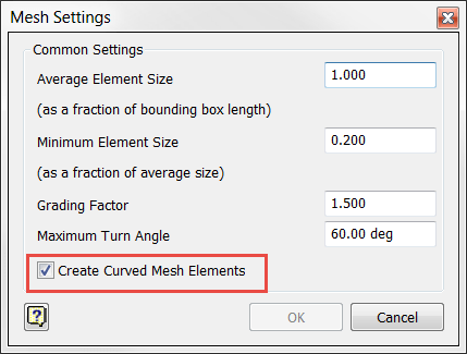
Basically, it adds an extra node to all the edges of the element. Instead of using a rigid tetrahedron, you will have a much more flexible parabolic shape that forms better to curved geometry.
-
- 1st Order (Unchecked)
-
- 2nd Order (Checked)
Observe the difference between 1st and 2nd order elements in the clamp with a course mesh applied.
-
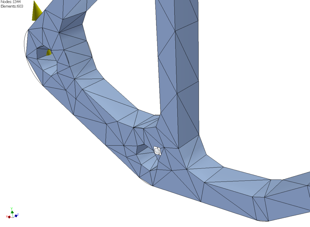
- Unchecked
-
- Checked
First, we will run the solver using the default mesh size to gain baseline results. Notice the areas shown in red are spread across only a few elements in each location. At times it can even look somewhat blotchy. This is a good indication there are too few elements in those locations for accurate stress results. Currently, we have a peak value of 99.63 MPa.

Global mesh size is the first option up for discussion. We’re going to make the average element size four times smaller. Remember that you can greatly increase solve times simply by cutting this number in half. We don’t have to worry about that in this case because the model is small. It only takes two seconds to solve.
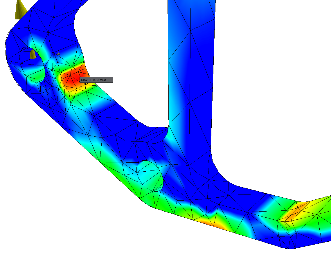
Notice in the plot that there are more elements used to calculate the stress results. Consequently, the stress values are going to be more accurate. Right now we are observing 100.6 MPa in the highest stress location.
 Let’s take that a step further and add local mesh control to the peak stress location only.
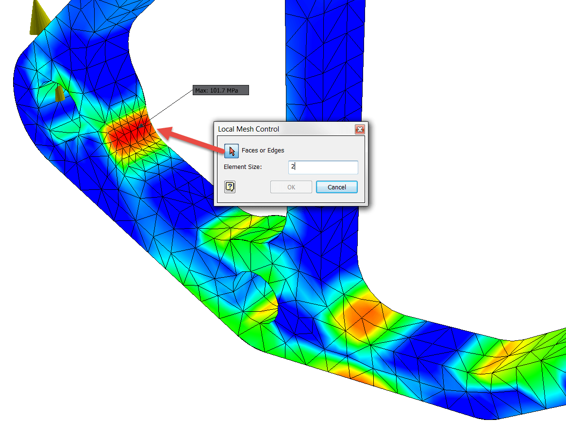
After running the solver, the stress result has increased to 101.7 MPa. We can continue to apply more elements to that area, however eventually the change in stress results will be nominal. In other words, we have converged on an accurate result. Adding more elements would only lengthen the solve time.
What if we are concerned with the stress values in some of the other areas of the model? We can either add mesh control to those locations as well, or we can use convergence settings. Convergence settings runs the solver several times until convergence has been met. Each time the solver runs, the high stress concentrations are refined, or in other words, additional elements are added. The low stress locations are left alone.
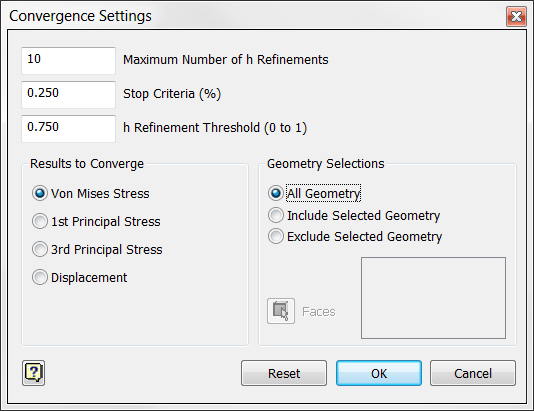
The maximum number of refinements can be any number. I like to enter a value of around 10. Chances are the solver is going to finish before it gets through that many iterations. Why do we need it? We don’t want to let the solver run forever due to a singularity in our stress results. In cases of singularity, the results will diverge instead of converge. This can happen when the highest stress is located on a sharp corner without a fillet. It can also occur when the highest stress is next to a rigid constraint.
The solver will stop when the difference between iterations is less than the stop criteria percentage. A value of 2% or less is reasonable.
There is also the option to choose the stress result type. Von Mises is commonly used and it will refine the stresses that are under both tension and compression. The 1st and 3rd principal stresses will only refine tensile and compressive stresses respectively.
-

- 1st Principal (Tension)
-

- 3rd Principal (Compression)
-

- Von Mises
High stress shown in blue (negative value)
Geometry selection enables us to select areas we are concerned with. Remember when I mentioned that singularity thing. This setting may help because we can then select the area(s) we are concerned with, and bypass disregarded stress locations that are error prone.

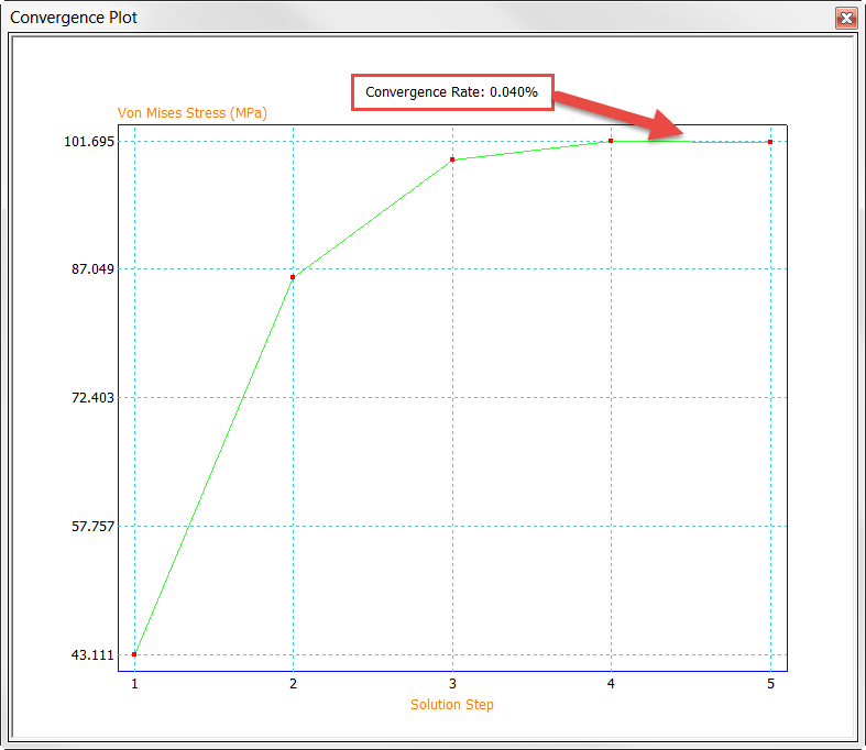
Once the solver is complete, there is the option to pull up a convergence graph. This shows the results for each iteration. It is the path to convergence. You can see the difference between the fourth and fifth iteration are within our stop criteria percentage of 0.25%.
That wraps up the third option for setting up your mesh. Follow these basic guidelines and you should have no problem coming up with accurate stress results in your own FEA studies. I hope that this article has been useful to you as we briefly discussed the options available for mesh creation in Autodesk Inventor Professional. Please feel free to contact me directly if you have any questions, comments, or suggestions. @jimbyrne7777
See you again soon!

(0)