Setting up your FEA studies is an intuitive process. You selected your material, applied loads and constraints, meshed the geometry, and finally solved the analysis. You have your results, but are they correct? Of course the results are correct, you followed all the steps, right? Let’s look at one of many ways to check the accuracy of those colorful looking plots you are so carefully examining. We will be focusing on reaction forces.
In a static analysis it is important that you define how your model is held down so it doesn’t produce free body motion during the solve. In other words, we need to make sure the part doesn’t move when the load is applied. I’ll demonstrate the wrong and the right way to accomplish this step.
We will use this example of the clamp I used in the previous blog for meshing. We are going to apply fixed constraints to two locations on the component. Then we will apply the load from the actuator acting on the clamp. You may already know these fixed constraints are a bad idea, but how do we know when observing the results?

Animating the behavior of the model is a great visual method for checking your setup. Be sure to change the settings of the plot to show an exaggerated deformation. This way it becomes much easier to understand the behavior of the geometry based on your boundary conditions. Keep in mind that this is still a visual method of checking your results. You may not want to rely on the naked eye only.
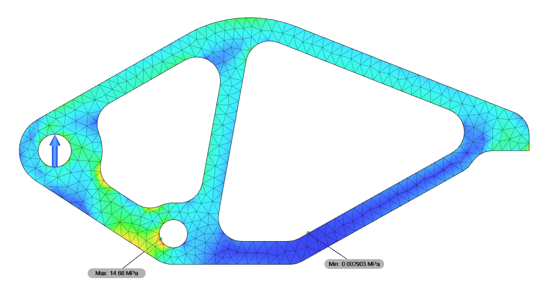
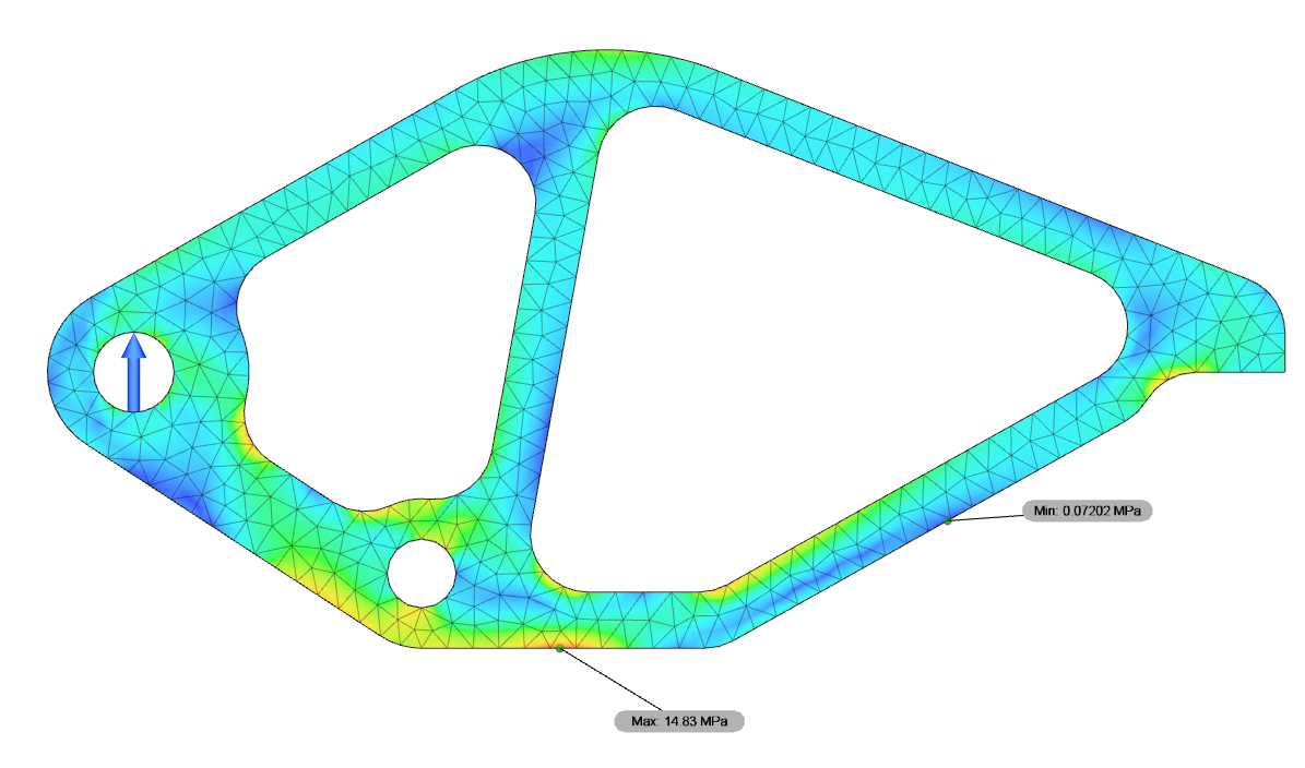
Looking at the stress plot we can see where the highest stress locations are on the model. At first glance this seems reasonable.
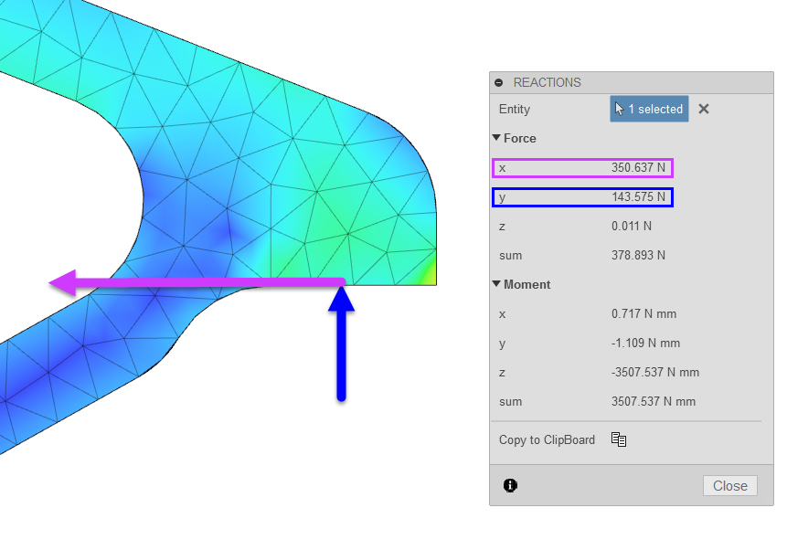
Another method of checking your results is by probing the reaction forces on the constrained geometry. Do those forces make sense? All FEA software applications provide this information. Let’s look at the flat face where the clamp comes down on the object. It makes sense that we are seeing a reaction force in the Y direction (although the value is low). Why are we witnessing an even larger reaction force in the X direction? You may very easily miss the fact that this clamp wants to deflect significantly in the both directions. Already we can see the fixed constraint is too rigid in this location.
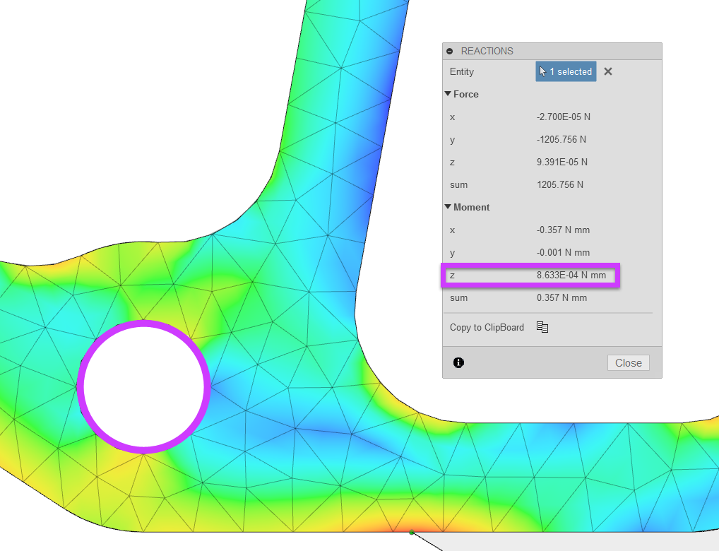
Now let’s have a look at the hole where the clamp is pivoting. In this case we’re focusing our attention on moment. Currently it’s reading 8719 N mm. In reality this hole is not fixed. It has the ability to rotate about the fastener. This again can have a large impact on the behavior of the surrounding geometry and ultimately affect the stress and displacement results.

Now that we understand the impact fixed constraints have on this model, we’re going to replace them with different types of constraints.
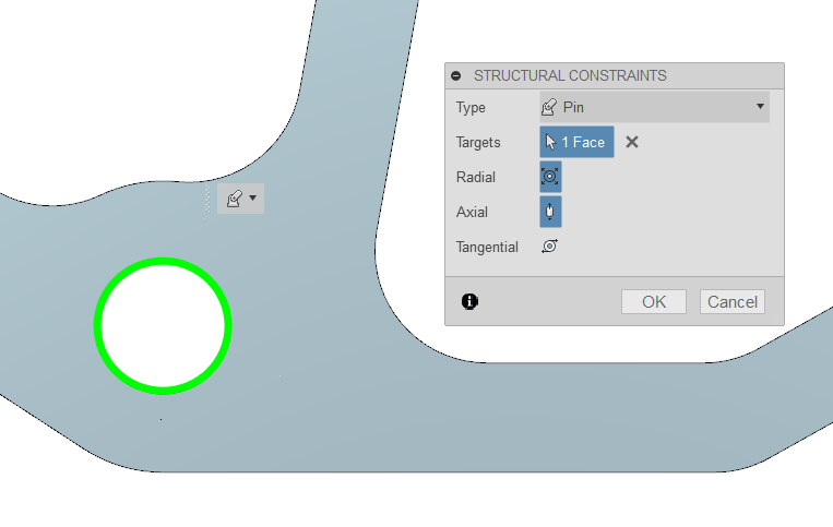
We will apply a pin constraint to the hole. This enables us to fix or free the radial, axial, or tangential directions of the cylindrical face.
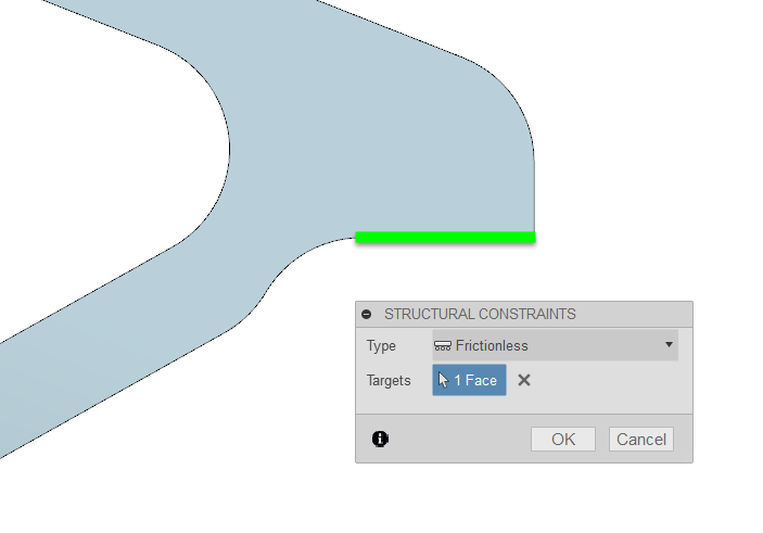
Next we have the flat face. Here we will add a frictionless constraint. This only allows motion parallel to the selected face.
Then we can rerun the solver and check our results! Right out of the gate we notice there are differences for displacement and stress. The exaggerated displacement plot shows a lot more deformation on the model (especially in the X direction).
Earlier the highest stress was on the pivoting hole which was fixed. The stress plot now shows the highest stress concentrations in other areas of the model.
Finally, we will check the reaction forces. How were they impacted by the changes in boundary conditions? The flat face now only shows a reaction force in the Y direction as expected. The value is also more realistic based on the location of the pivoting hole.

Speaking of the pivoting hole. We can see the moment is close to zero with the pin constraint.
There are two key takeaways for this article. As you have seen, the types of restraints you use have a significant impact on the results for stress and displacement. And second, be sure to take advantage of the reaction forces on applied constraints to check your results and gain valuable information about your design!

(0)