Do you remember the first time you setup and ran a FEA analysis? More than likely, the mesh you used was made up of lots of solid tetrahedrons or hexagons. It doesn’t take long before you notice there are several options for mesh control and idealization. This article won’t cover all the different element types available. Let’s focus on the shell element for now. What is it? Why use it?
What is the shell element?
As you probably already know, solid elements are shapes that make up a volume. Shell elements on the other hand have no volume. They are analogous to zero thickness surface geometry. The solver calculates the thickness of the geometry which is either input by the user or in some cases automatically applied based on the model. This of course means that shell elements are only applicable for thin parts such as sheet metal or plastic bottles.
-

- Solid Element
-
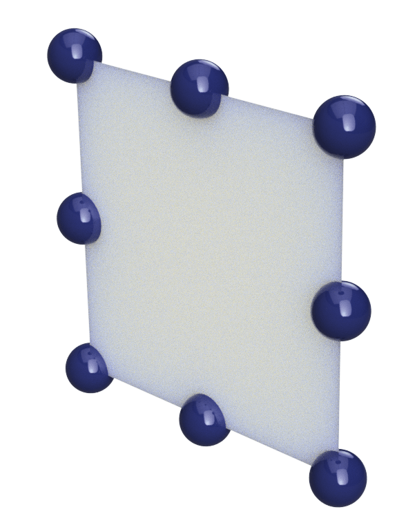
- Shell Element
Why should I use them?
Shell elements solve very quickly. The following images display solid and shell elements for the same component. The solid mesh has 3.5 times the number of nodes using the same size element. Then we also need to consider large aspect ratios on solid elements for thin-walled components. They can be easily distorted. For this reason, more elements need to be added and the ratio gets even bigger, solve times longer. Solid elements also exaggerate the stiffness of the model since they don’t account for bending, which leads to the next reason to use shells.
-
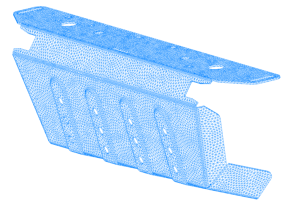
- Solid Elements (130,000 Nodes)
-
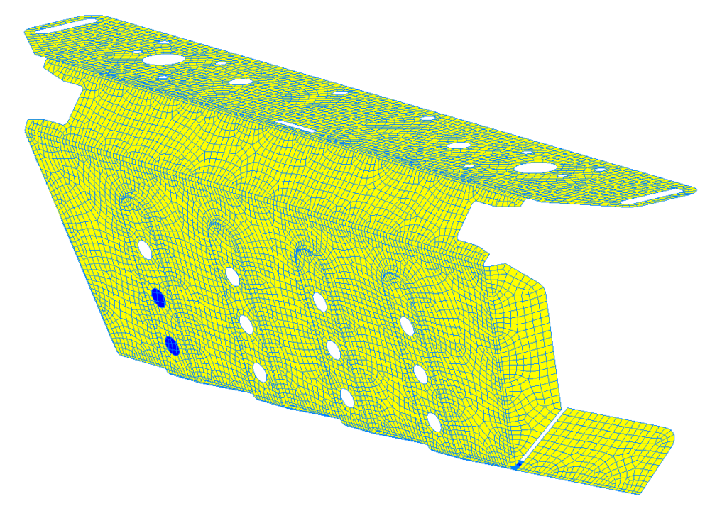
- Shell Elements (37,000 Nodes)
Shell elements produce additional results for membrane and bending stress. The nodes on solid elements only have three degrees of freedom for translation in the XYZ directions. Shell elements have additional degrees of freedom for the moment or rotation of each node in XYZ. It provides a much more accurate mathematical model for calculating the stiffness of the geometry.
-

- Solid Element Node (3 DOF)
-
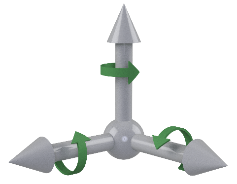
- Shell Element Node (6 DOF)
Hopefully that’s enough information to gain the confidence you need to begin using shell elements as opposed to solid elements for your thin walled components. It will save on solve time which in turn will enable you test more ideas and better optimize your designs.

(0)