Here we have a boat (partially submerged solid) moving through water. As any other aerodynamics analysis, we generally keep the boat still and move the fluid around it.
Follow the steps below, which include the model setup while applying the best practices you learnt from setting up a free surface analysis.
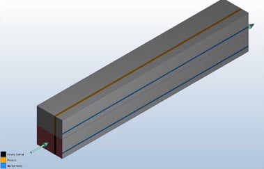
1. CAD Model
In your CAD software, model the boat in a ‘box’:
- Split this volume into two parts
- Upper part (To capture water/air boundary). This represents the air
- The bottom part. This represents the water
- Leave a good length for the outlet (5X the diameter of the flow channel)
- Leave enough space on the sides of the boat to capture the turbulence around it
- If you can utilize symmetry, split the whole model into two even parts and use only half of the model
- Launch into CFD
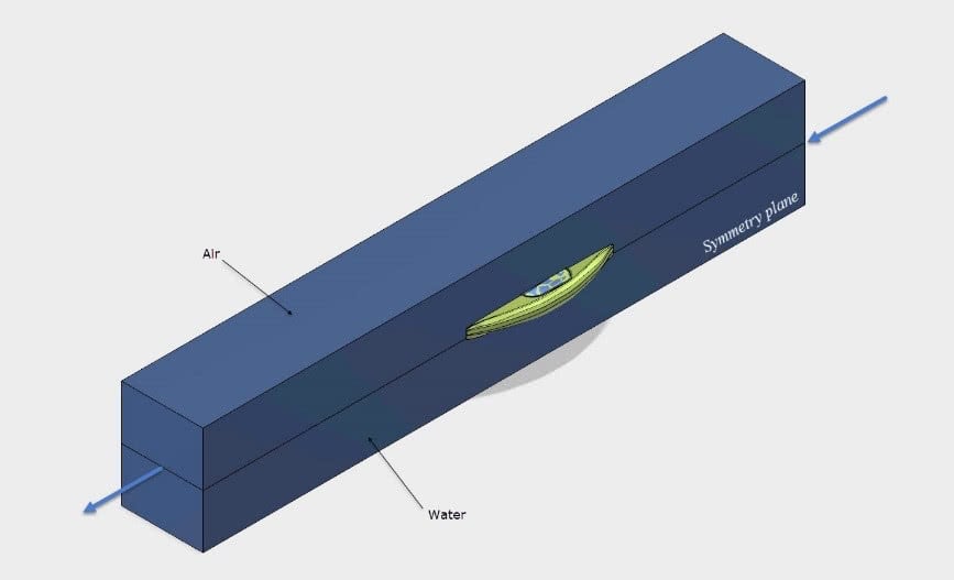
Image 2: 1/2 CAD Model
2. Materials
Define the solid (boat) as well as the fluid (water) materials.
a. Solid
Assign a solid material to the boat hull
b. Fluid
Assign water to the two parts of the box volume (this will make sense later)
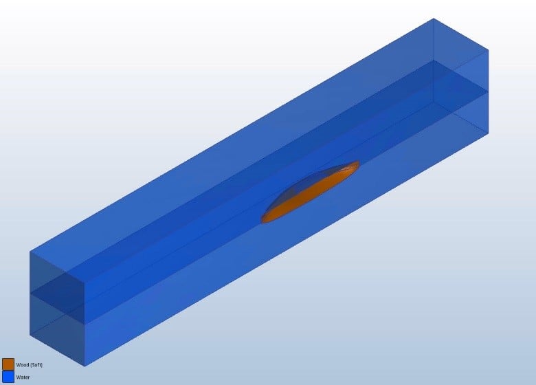
Image 3: Materials
Note that the following error message will pop up if you try to assign two touching fluids (do not do this):
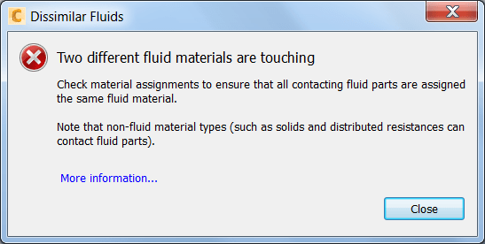
Image 4: Touching fluids error
3. Boundary conditions
Since half of the model is considered, a symmetry boundary should be applied on the symmetry plane.
| Location | BC |
| Inlet | Velocity |
| Outlet | Velocity (note the direction) |
| Opening Sides | Pressure = 0 or a velocity component |
| Symmetry plane | Slip / Symmetry |
-
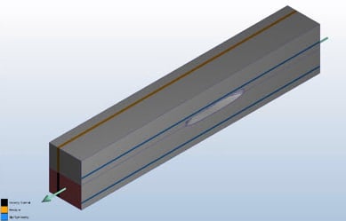
- Image 5: Front view
-
- Image 6: Rear view
4. Initial conditions
We need to initialize the model by assigning initial conditions to the water volume.
- Change the Selection Mode to Volume
- Assign Height of Fluid (HOF) to the lower water volume (the upper has nothing assigned and will begin the analysis empty)
- An Initial Velocity equal to that at the inlet and outlet. This helps initialize the motion state of water

Image 7: Initial Conditions
5. Mesh
Manual meshing was used for this model.
Meshing is very important as it controls the model accuracy and also contributes to a good visualization of the results of free surface analyses. Be sure to:
- Refine the mesh in regions where water and air interact
- Make sure to define a fine and uniform mesh distribution at the water/air interface
- For regions where water would be turbulent, apply a good mesh using regions:
- Either in the CAD software while creating a CAD region around the boat and then assigning a small mesh element size to it in CFD
Image 8: Cad’ed Region
2. Or in CFD by adding a Mesh Refinement Region
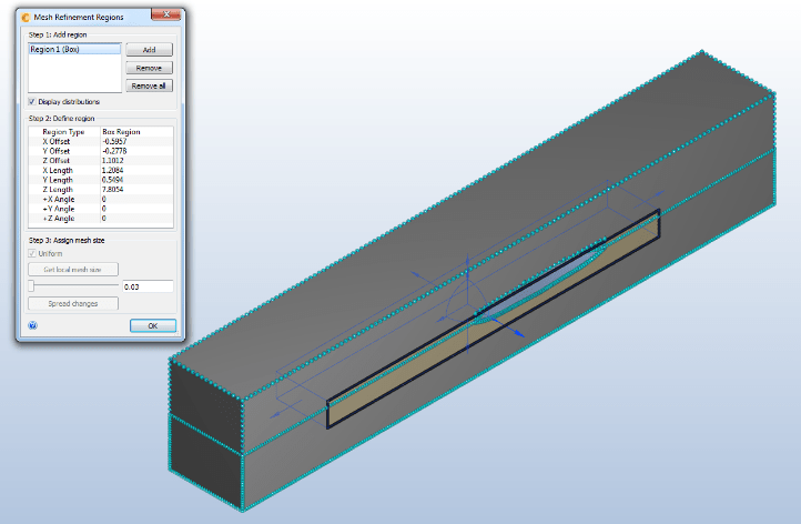
Image 8: Cad’ed Region
- Unless you are running heat transfer analysis, suppress the boat from the mesh. Its surfaces still can be refined while switching to surface selection and also displayed in the results

Image 10: Mesh
6. Solve
On the Solve dialog, enable ‘Free Surface’

Leave everything the same as default according to the Help documentation of Free surface