Introduction and Background
Heat flux estimation on solid surfaces (external and internal) has been plagued by two issues. First, gradient-based estimation suffers when the mesh is not extremely fine near the surface, resulting in inaccuracy. This is primarily due to linear interpolation functions of the finite element, whose first derivatives are discontinuous at the element edges. Second, linear elements, whose first derivatives are discontinuous at the element edges, is a contributor to inconsistency.
Problem Resolution
The remedy is to introduce a post-processing step, where the weak form of the governing equations is constructed at the finite element boundaries and solved using the current temperatures to extract the natural condition value of the flux needed to maintain the solved or prescribed temperatures. The weak form values of the equations are assembled onto the nodes (referred to as residuals). These residuals are computed for each surface node based on elements of parts sharing the node. Thus, a surface node will have as many residual values as the number of parts associated with it.
The challenge for this procedure is to compute the assembled nodal equation residuals on a surface, then distribute these values in a consistent manner so that for any given solid body, the sum of the distributed nodal residuals (on all surfaces) is equal to the heat generated within, henceforth called the volume surface balance requirement (VSB).
- For external surfaces, boundary conditions must be applied such that there is no conflict with the boundary conditions on adjoining surfaces.
- For example, a temperature boundary condition cannot overlap to conflict with a heat flux boundary condition on an adjoining surface. With this convention, the non-edge nodal residuals (NENR) summed up will yield the correct heat flux on such surfaces.For surfaces shared by two parts, internal surfaces, the nodal residuals on the edges (ENR) must be shared with any other adjoining internal surfaces to satisfy the VSB. The procedure is to sum the NENR values first, then add to it the apportioned values from the ENR.
Remarks:
- No area-based integration is used to compute surface fluxes.
- For optimum accuracy, frequently to within machine round-off, the solution of the temperature field should be sufficiently converged. This is often the case for solid parts with constant conductivity.
- For transient phenomena and materials with variable properties, the solution at each time step should have a sufficient number of inner time steps for optimum accuracy. Note that the transient storage or discharge of energy of a part is not accounted for in the residuals. Therefore, any non-zero total surface flux of a part (based on the residuals as calculated above) is a combination of any energy generation and storage/discharge within.
Notes:
- Currently available for CFD 2019.1.
- Currently not enabled for the motion module.
- To turn off this feature, use the flag “resid_heat_flux” set to 0.
Wall Calculator Widget UI Change – An Example
The Wall Calculator Widget output page changed slightly to report the heat flux on a surface, in terms of the part ID that the heat is leaving (if applicable) and the part ID that the heat is flowing to (if applicable). All values are given as absolute quantities, but the sense of the heat flow is given in terms of part(s) ID(s) a given surface is sharing. In the case of an external surface, only a single part ID is given with the sense FROM or TO that part.
The following example shows how the new wall calculator method resolves the issue of consistency in energy balance and heat flow direction across internal boundaries.

The image above shows the 2D model problem setup with materials and boundary conditions.
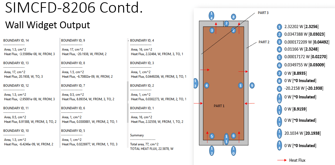
Above, the image shows the new values of the heat flow across the surfaces of the model, on the left. The right side of this image also shows the flux values across each surface in boldface and compares with the existing method to highlight the improvements, particularly for the internal surfaces.
Try this example in a previous version of CFD and you’ll really appreciate the improvements in accuracy!
This post was done in collaboration with Syed Husain

(0)